Switch-mode self-coupling auxiliary power device

Inactive Publication Date: 2006-09-12
TAMIRAS PER PTE LTD LLC
View PDF6 Cites 73 Cited by
  • Summary
  • Abstract
  • Description
  • Claims
  • Application Information

AI Technical Summary

Benefits of technology

[0011]As described above, when the load signal represents a high or normal load condition, a voltage on the auxiliary winding charges the maintaining capacitor and high voltage auxiliary winding does not working, contrary when the load signal represents a low load condition, the voltage only on the high voltage auxil

Problems solved by technology

However, when the conventional power supplier containing a PFC (Power Factor Correction) is used with information appliances, conformation to the power saving standards does not always occur, so as to cause a lot of bother.
However, this method may induce a voltage lower than the normal

Method used


Image

  • Switch-mode self-coupling auxiliary power device
  • Switch-mode self-coupling auxiliary power device
  • Switch-mode self-coupling auxiliary power device

Examples


Embodiment Construction

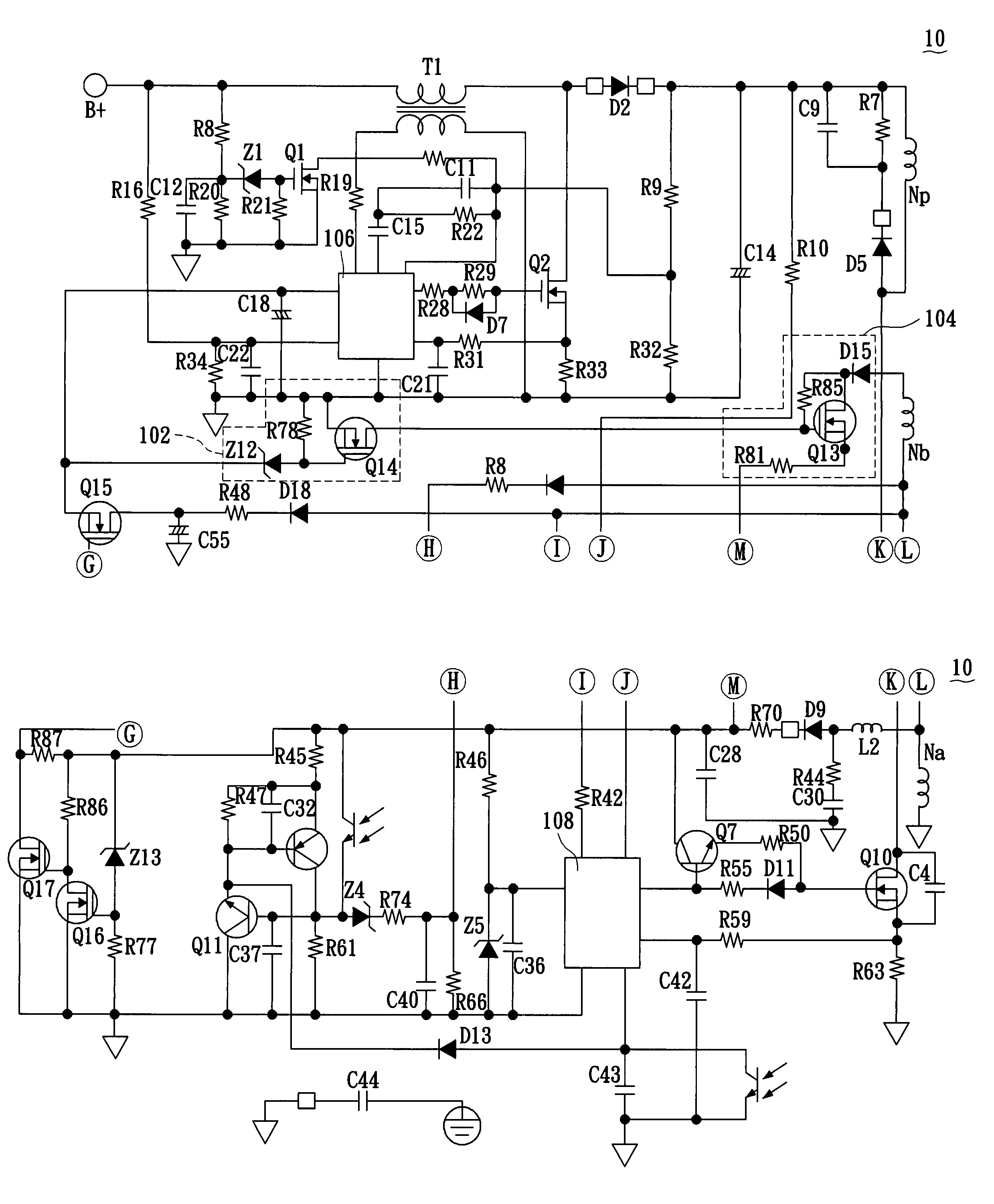
[0016]References are made to FIGS. 2A to 2C showing the circuit diagrams of a first embodiment in the present invention. A switch-mode self-coupling auxiliary power device is used in a power supplier for charging a maintaining capacitor C28 so as to provide the operation power needed by a controller 108 and includes the following elements. A transformer Tr has a main winding Np and a sub-winding Ns, which divide the power supplier into a primary side circuit 10 and a secondary side circuit 20. The transformer Tr also has an auxiliary winding Na connected to the maintaining capacitor C28, and a high voltage auxiliary winding Nb. A control circuit 102 is connected to a PFC (Power Factor Correction) 106 through a detection capacitor C18 to sensing PFC ON or OFF state. The PFC 106 ON or OFF state is used to output a load signal to the control circuit 102 according to the load of the circuit, and outputs a control signal according to the load signal. An energy transmitting circuit 104 is...


PUM


Abstract

A switch-mode self-coupling power device additionally increases a set of high voltage auxiliary winding in the transformer and increases a control circuit and an energy transmitting circuit in the primary side circuit of the conventional circuit. When the load is too low, the control circuit may control the energy transmitting circuit according to the variation of the load so that the voltage of the high voltage auxiliary winding can be transmitted to a controller for operation through the energy transmitting circuit. Therefore, the design of PWM controller (pulse width modulation controller) auxiliary power circuit according to the present invention, which is not limited by the magnitude of a dummy load at the secondary side of the transformer, can conform to international regulations and is a product with industrial purpose and conforming to green mode.

Description

BACKGROUND OF THE INVENTION[0001]1. Field of the Invention[0002]The present invention is related to a switch-mode self-coupling auxiliary power device, which is an assistant power device providing an enough voltage power to a controller under a low load.[0003]2. Description of Related Art[0004]According to the tendency of information appliances, in addition to powerful functions and low price, power saving is an important subject. For conforming to the requirement for power saving, many standards have are established; for example, GEEA of Europe stipulates that a power converter for a LCD TV should have a standby power of less than 1 W, and ENERGY STAR of U.S.A. also stipulates that a power converter with an output power ranging between 10 to 250 W should have a no-load power less than 0.75 W. Therefore, when improving the material used by the manufacturer for achieving a power-saving effect, the power converter is also an important key point in power saving. However, when the conve...

Claims


Application Information

Patent Timeline
IPC IPC(8): H02M3/335
CPCH02M3/33507Y02B70/16H02M2001/0032H02M2001/0006H02M1/0006H02M1/0032Y02B70/10
Inventor LIN, FENG-HSULU, WEN-YU
Owner TAMIRAS PER PTE LTD LLC
Why Eureka
Try Eureka