
Method and apparatus for timing recovery based on dispersion characterization and components therefor

a timing recovery and dispersion technology, applied in the field of communication system timing recovery methods and apparatuses, can solve the problems of long delay spread multipath, fractionally spaced equalizers, and optimal timing recovery

Inactive Publication Date: 2006-09-12
FOX ENTERTAINMENT GROUP
View PDF1 Cites 10 Cited by
  • Summary
  • Abstract
  • Description
  • Claims
  • Application Information

AI Technical Summary

Benefits of technology

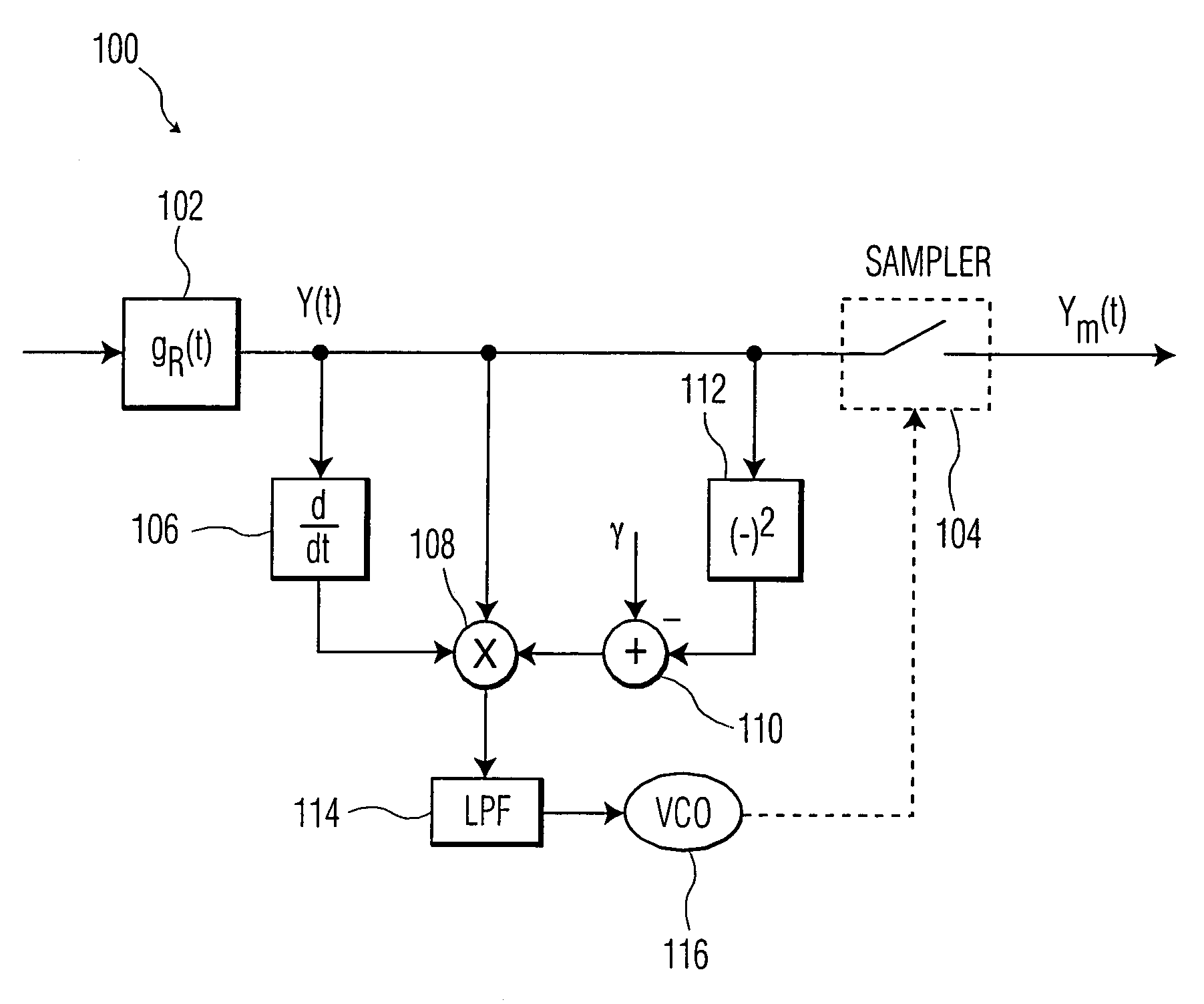
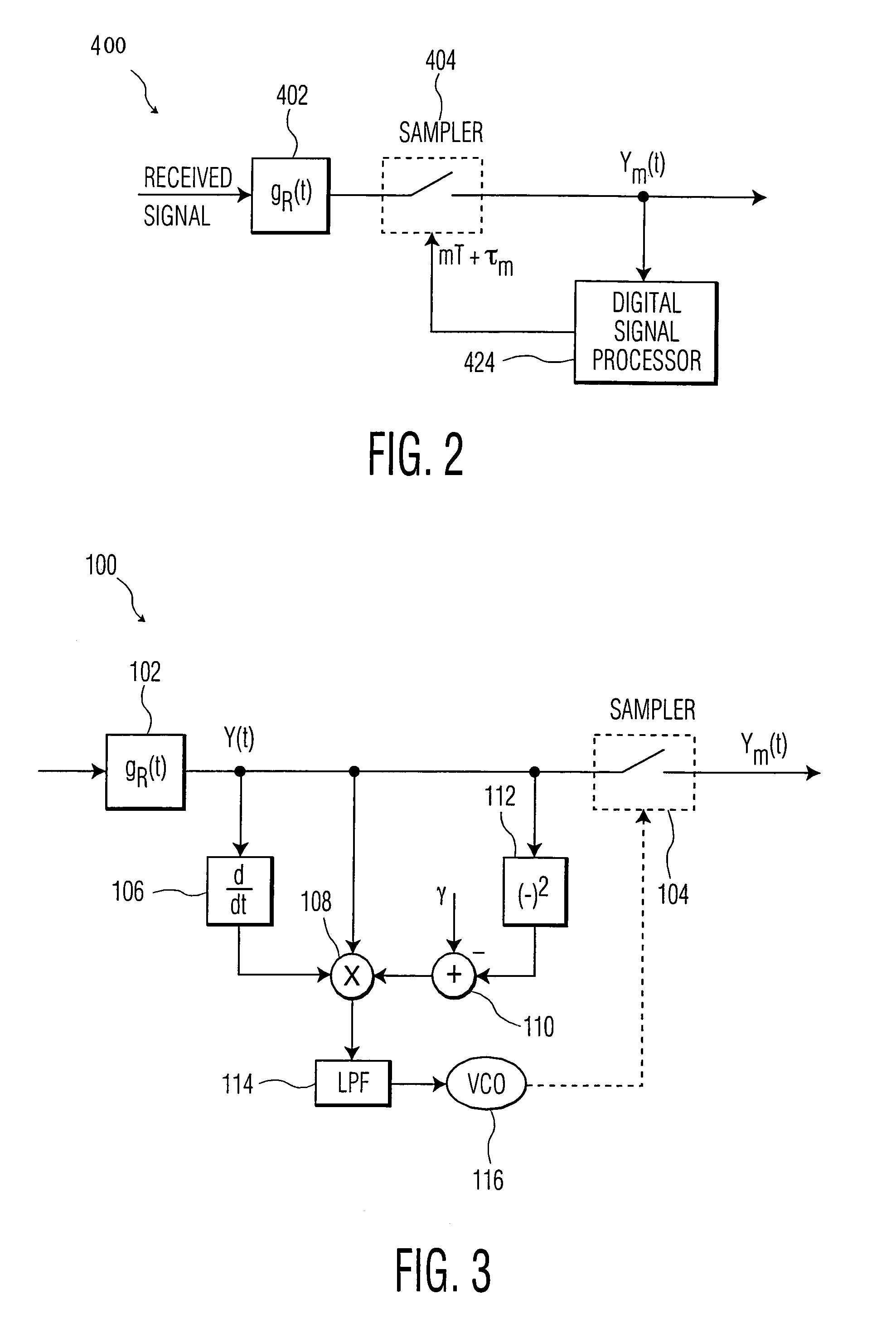
"The present invention provides a method and apparatus for extracting a digital symbol stream from a filtered signal output by a sampling device. The method involves generating a timing offset signal by approximating the derivative of the symbol stream and producing a constant representative of an expected symbol stream. The timing offset signal is then filtered to generate a noise-free signal. The invention aims to overcome the deficiencies of current methods and apparatuses by minimizing the dispersion of the received signal. The technical effects of the invention include improved timing recovery, reduced noise, and improved signal quality."

Problems solved by technology

Recent efforts in developing digital radio / video broadcasting systems, e.g., HDTV broadcasting systems, have highlighted the problem of optimal timing recovery as a significant issue in digital receiver design.
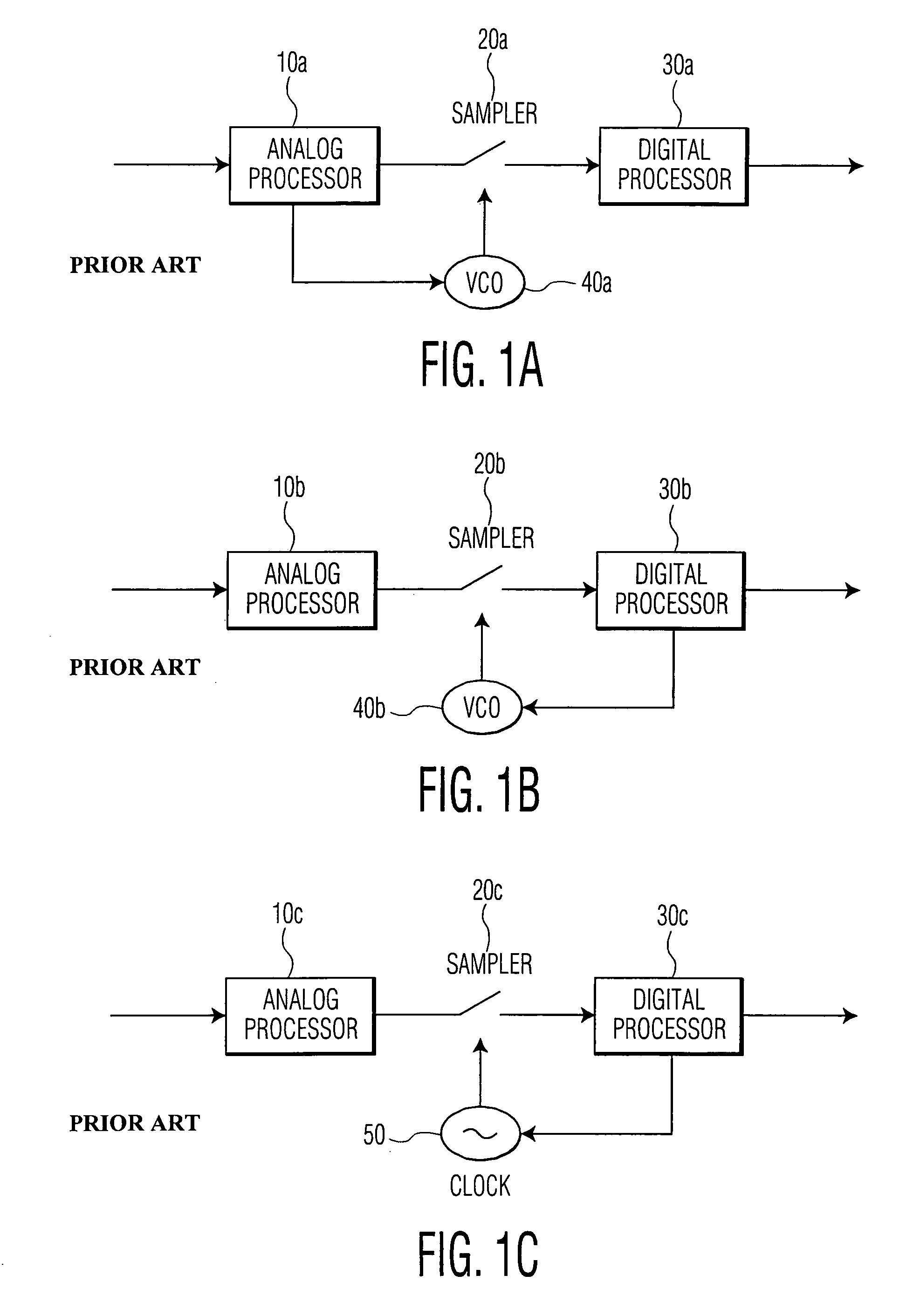
More specifically, one of the features of digital media broadcasting channels is long delay spread multipath; the traditional approach to this problem, i.e., inclusion of fractionally spaced equalizers that are insensitive to timing phase in each receiver, is impractical in consumer electronics receivers and the like.
The problem of timing recovery consists of estimation of the timing frequency and the optimal timing phase.
Both the Early-Late Gate and the ML methods were developed based on the assumption that there are no channel dynamics; the validity and performance of these methods are difficult to ascertain in the presence of several additional nontrivial channels, i.e., a multipath channel.
However, the application of the constant modulus algorithm (or the minimization of the dispersion of the received signal) heretofore has not been applied, or even proposed, as a solution for timing phase recovery for a single antenna structure subject to substantial multipath.
None of these circuits are explicitly configured for blind timing recovery.

Method used


Image

  • Method and apparatus for timing recovery based on dispersion characterization and components therefor
  • Method and apparatus for timing recovery based on dispersion characterization and components therefor
  • Method and apparatus for timing recovery based on dispersion characterization and components therefor

Examples


Embodiment Construction

[0030]Illustrative embodiments and exemplary applications will now be described with reference to the accompanying drawings to disclose the advantageous teachings of the present invention. While the present invention is described herein with reference to illustrative embodiments for particular applications, it should be understood that the invention is not limited thereto. Those having ordinary skill in the art and access to the teachings provided herein will recognize additional modifications, applications, and embodiments within the scope thereof and additional fields in which the present invention would be of significant utility.

[0031]The inventive method and corresponding apparatus advantageously provides a techniques and structure permitting timing recovery through minimization (or maximization) of the dispersion of the received signal; any apparatus, whether harware or software, that implements such an approach to the problem of timing recovery, that is, to the problem of dete...


PUM


Abstract

The present invention provides a method for generating a timing offset signal applied to a sampling device for recovering a symbol stream from a broadcast signal by characterizing the dispersion of received signal. Preferably, the method includes steps for generating a derivative signal approximating the derivative of the symbol stream, producing a constant representative of an expected symbol stream, and multiplying the derivative signal, the constant, and a signal one of corresponding to and approximating the symbol stream to thereby generate the timing offset signal. A dispersion characterizing receiver and a digital signal processor employed therein are also described.

Description

BACKGROUND OF THE INVENTION[0001]1. Field of the Invention[0002]The present invention relates to timing recovery methods and apparatuses in communication systems. More specifically, the present invention relates to methods and corresponding apparatus for timing recovery based on dispersion in the received signal. Software and components for implementing the novel methods according to the present invention are also disclosed.[0003]The instant patent application is based on Provisional Patent Application No. 60 / 241,274 of Oct. 17, 2000, which application is incorporated, in its entirety, by reference.[0004]2. Description of the Related Art[0005]In any communication system, it is necessary to synchronize the clock at the receiver with the clock at the transmitter, a process that is commonly called synchronization or timing recovery. In other words, timing recovery is the derivation of a timing signal from the received signal. Timing recovery can be accomplished by a variety of methods,...

Claims


Application Information

Patent Timeline
Patent Type & Authority Patents(United States)
IPC IPC(8): H04L7/00H03L7/00H03L7/091H04L7/02H04L7/027H04L7/033
CPCH03L7/00H03L7/091H04L7/0272H04L7/0054H04L7/0062
Inventor BALAKRISHNAN, JAIGANESHSETHARES, WILLIAM ACHUNG, WONZOOMARTIN, RICHARDJOHNSON, JR., C. RICHARD
Owner FOX ENTERTAINMENT GROUP
Learn More