Heat exchanger for high purity fluid handling systems

a heat exchanger and fluid handling technology, applied in the field of compact heat exchangers, can solve the problems of increasing the potential for particle build-up and contamination of the etching fluid, increasing the heat required to raise and maintain the temperature of the etchant, and increasing the risk of contamination, etc., to achieve convenient maintenance and facilitate high-temperature heating of high-purity and/or corrosive fluids.

Inactive Publication Date: 2006-09-12
APPLIED INTEGRATED SYST
View PDF3 Cites 22 Cited by
  • Summary
  • Abstract
  • Description
  • Claims
  • Application Information

AI Technical Summary

Benefits of technology

[0010]The present invention overcomes the problems associated with the prior art by providing a novel heat-exchanging device. The invention facilitates high temperature heating of high-purity and / or corrosive fluids by utilizing temperature resistant tubing having corrugated bends formed therein. The unit is compact, inexpensive, expandable, and easy to maintain.
[0013]The thermal reservoir(s) of the various heat exchangers are heated and / or cooled in a variety of ways. In a particular embodiment, at least one heater is secured to the thermal reservoir(s). In a more particular embodiment, the heater is a cartridge heater disposed in or between one or more plates or thermal reservoirs of the heat exchanger. In an alternate embodiment, thermoelectric chips are coupled to the outside of one or more thermal reservoirs. Optionally, a heat sink can be secured to the thermal reservoir to prevent the thermoelectric chips from overheating, as well as, to regulate the temperature within the thermal reservoir.

Problems solved by technology

Because both the process temperatures and the heat capacities of the etching fluids are relatively high, a rather large amount of heat is required to raise and maintain the temperatures of the etchants.
Therefore, because etching chemicals, such as hydrofluoric acid, are harsh and corrosive, the etching fluid must not come in contact with any portion of the heat exchanger which could corrode and / or dissolve, thereby introducing contaminants into the etchant.
While the turbulence caused by the inserts facilitates increased thermal transfer between the heat exchanger and the fluid, the inserts also cause “dead zones” within the fluid flow, increasing the potential for particle build-up and contamination of the etching fluid.
In addition, it is also hard to form tight bends in known tubing materials.
This creates several problems when designing and manufacturing heat exchangers, wherein tubing typically includes multiple bends.
First, known inert tubing is easily kinked, and cannot therefore be bent into small diameter bends.
Rather, such tubing requires a large bend radius, and is therefore often bent outside of the heat exchanger, thereby reducing the heating efficiency of the heat exchanger.
In either situation, because of the large bend radii of plastic tubing, less tubing can be used per unit surface area of the heat exchanger, thereby reducing the thermal efficiency of the heat exchanger.

Method used


Image

  • Heat exchanger for high purity fluid handling systems
  • Heat exchanger for high purity fluid handling systems
  • Heat exchanger for high purity fluid handling systems

Examples


Embodiment Construction

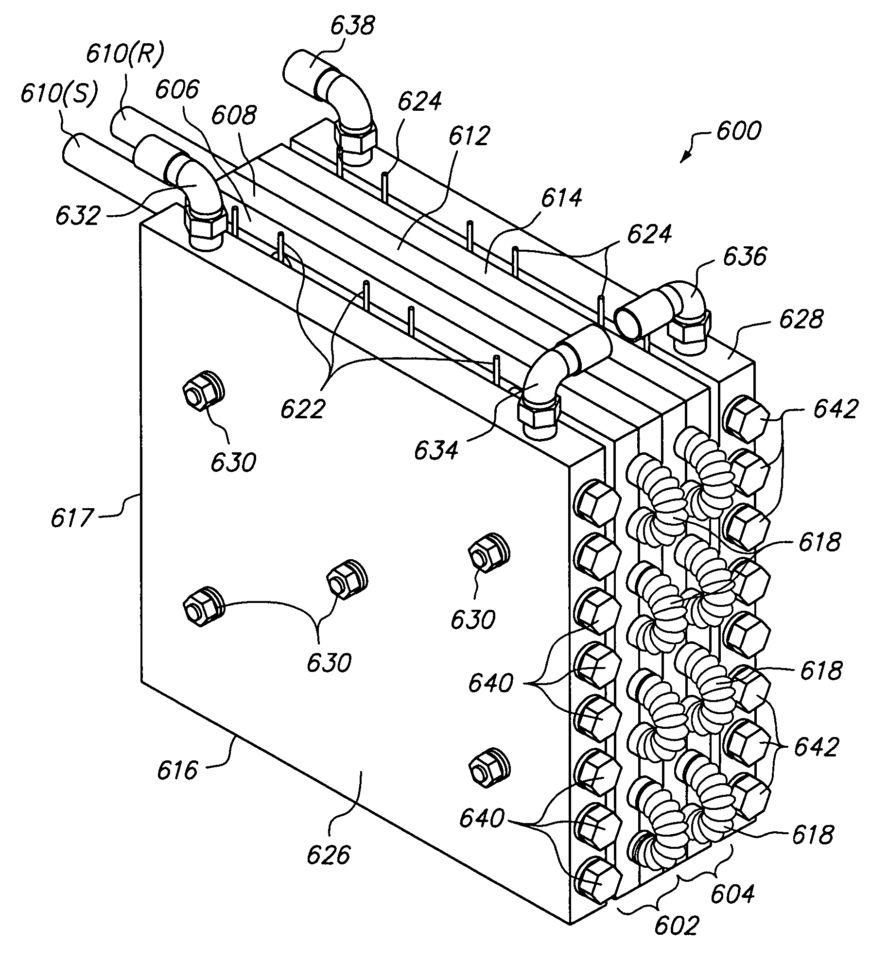
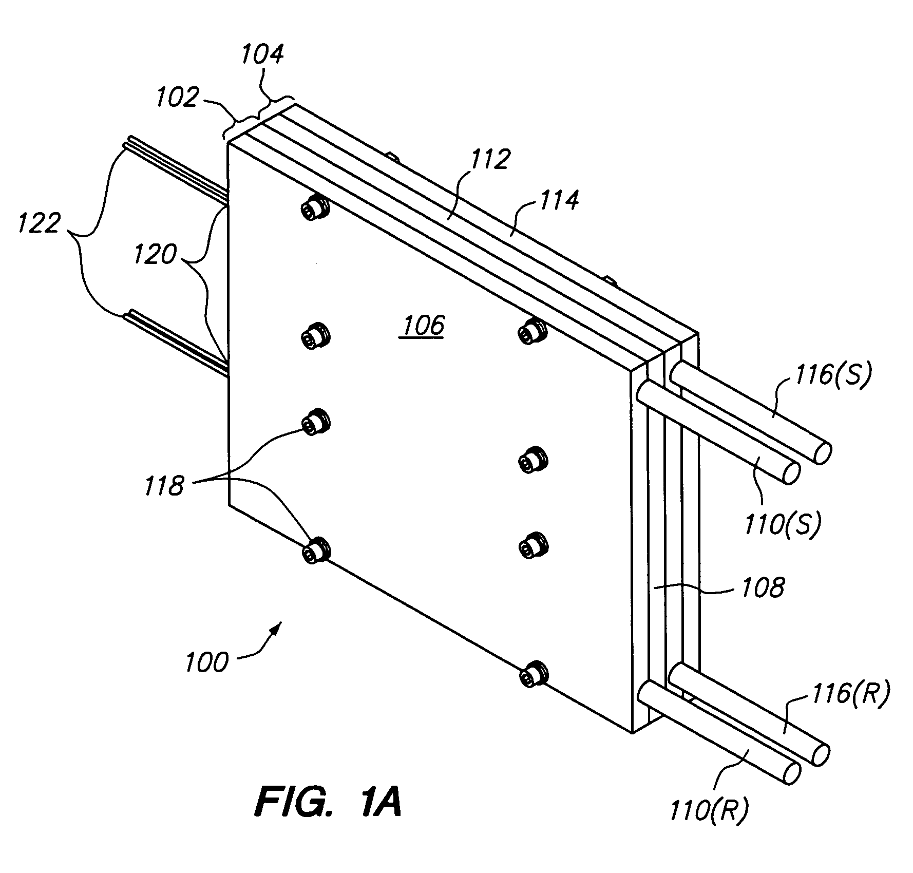
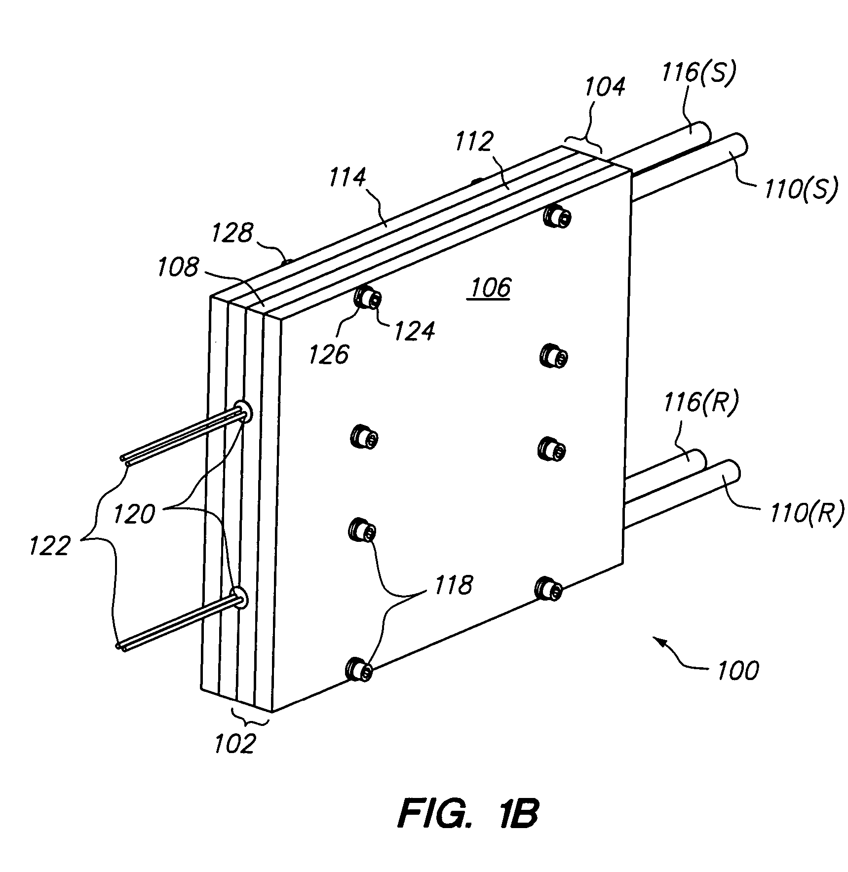
[0027]The present invention overcomes the problems associated with the prior art, by providing a novel heat exchanger that utilizes temperature resistant, corrugated tubing to improve heat transfer between the heat exchanger and fluid, while simultaneously remaining compact, inexpensive, and easy to maintain. As used herein, “corrugated tubing” is understood to include tubing having convoluted sections formed therein. In the following description, numerous specific details are set forth (e.g., particular heat sinks, particular types of heating / cooling devices, particular fasteners, etc.) in order to provide a thorough understanding of the invention. Those skilled in the art will recognize, however, that the invention may be practiced apart from these specific details. In other instances, details of well-known fluid handling practices (e.g., supply and return pipe routing, electrical routing and control, heat exchanger mounting methods, etc.) and components have been omitted, so as n...


PUM

PropertyMeasurementUnit
Temperatureaaaaaaaaaa
Diameteraaaaaaaaaa

Abstract

A novel heat exchanger includes a thermal reservoir and a tube, the tube having straight sections and corrugated bends, and being in thermal contact with the thermal reservoir. The thermal reservoir has a first plate and a second plate fixed to the first plate. The first plate has a channel formed therein with straight sections to receive the straight sections of the tube, and curved sections for receiving the corrugated sections of the tube. The second plate has a channel formed therein as well that is complementary to the channel of the first plate. The heat exchanger is heated by one or more cartridge heaters. In a particular embodiment, two thermal reservoirs are fixed to one another and the cartridge heaters are disposed in channels formed therebetween. Optionally the thermal reservoirs can be heated or cooled by thermoelectric chips, and can include one or more heat sinks.

Description

RELATED APPLICATIONS[0001]This application is a divisional of prior U.S. patent application Ser. No. 10 / 116,721 filed Apr. 3, 2002 now U.S. Pat. No. 6,782,195 by the same inventors, which is incorporated herein by reference in its entirety.BACKGROUND OF THE INVENTION[0002]1. Field of the Invention[0003]The present invention relates generally to heat exchanger devices, and more particularly to a compact heat exchanger with corrugated polymeric tubing for use with high purity and / or corrosive fluids.[0004]2. Description of the Background Art[0005]Many industries require the use of heat exchangers to regulate the temperature of high purity and / or corrosive fluids. For example, microchip fabrication within the semiconductor industry requires heating and temperature regulation of the etching solutions used to etch silicon wafers and microcircuit lines. Because both the process temperatures and the heat capacities of the etching fluids are relatively high, a rather large amount of heat is...

Claims


Application Information

Patent Timeline
IPC IPC(8): F24H1/10F24H1/16F24H4/02F25B21/04F28D7/00F28D20/00F28F21/06
CPCF24H1/162F24H4/02F25B21/04F28D20/0034F28F21/062F28D7/0041Y02E60/142Y02E60/14
Inventor ABRAS, ALEXEI D.TAGHIPOUR, SAEED
Owner APPLIED INTEGRATED SYST
Why Eureka
Try Eureka