Polarization mode dispersion compensating apparatus, system, and method

a compensation apparatus and dispersion technology, applied in the field of optical communication systems, can solve the problems of small pmd values, increased bit error rate (ber), and polarization mode dispersion (pmd)

Active Publication Date: 2006-09-12
CIENA
View PDF11 Cites 26 Cited by
  • Summary
  • Abstract
  • Description
  • Claims
  • Application Information

AI Technical Summary

Benefits of technology

[0020]Control of the PMD may be further achieved by minimizing a sum of the squares of the first, second, and third detection signals.
[0021]Another polarization mode dispersion compensating system according to the invention includes: a polarization mode dispersion compensator optically coupled to an input port and receiving an input optical signal having polarization mode dispersion, said polarization mode dispersion compensator having a variable polarization mode dispersion; a Q detector operatively coupled to said polarization mode dispersio...

Problems solved by technology

Polarization mode dispersion (PMD) is a well-known problem caused by the undesired, residual birefringent properties of optical fibers.
Moreover, there are a variety of existing fiber plants having fibers not optimized to reduce PMD.
Such large DGD values can cause optical signal pulses (composed of both principal polarization states) to broaden to such an extent that intersymbol interference occurs and the bit error rate (BER) rises.
In a...

Method used


Image

  • Polarization mode dispersion compensating apparatus, system, and method
  • Polarization mode dispersion compensating apparatus, system, and method
  • Polarization mode dispersion compensating apparatus, system, and method

Examples


Embodiment Construction

[0031]The following detailed description of the invention refers to the accompanying drawings. The same reference numbers in different drawings identify the same or similar elements. Also, the following detailed description does not limit the invention. Instead, the scope of the invention is defined by the appended claims and equivalents thereof.

[0032]The expression “optically communicates” as used herein refers to any connection, coupling, link or the like by which optical signals carried by one optical system element are imparted to the “communicating” element. Such “optically communicating” devices are not necessarily directly connected to one another and may be separated by intermediate optical components or devices.

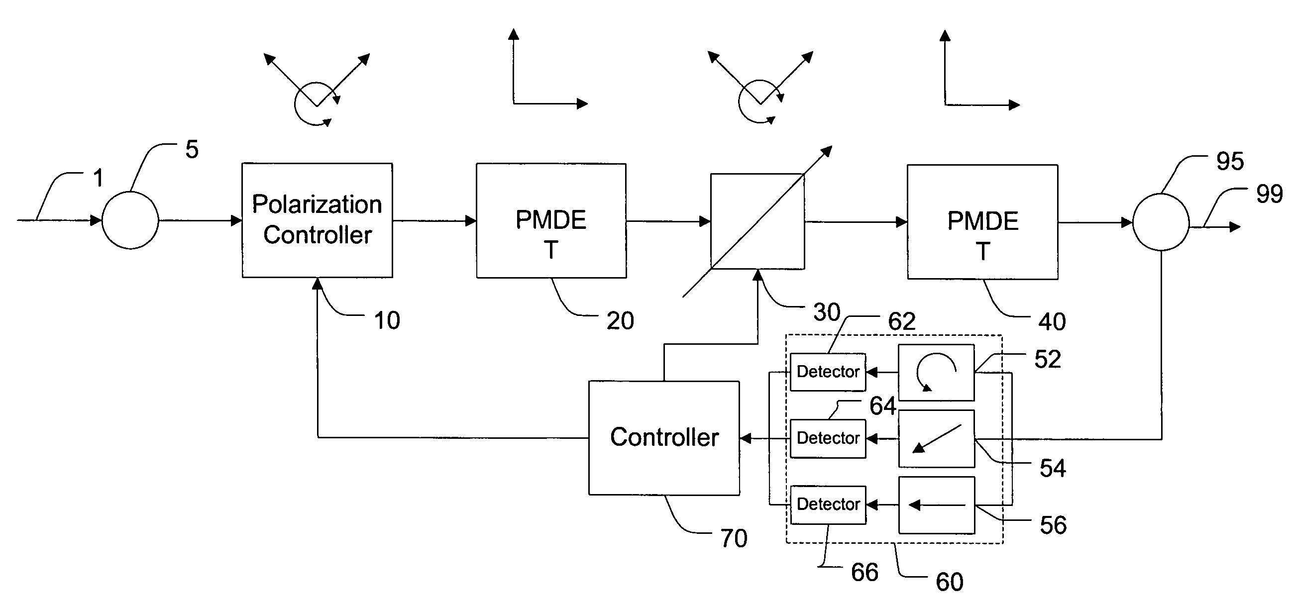
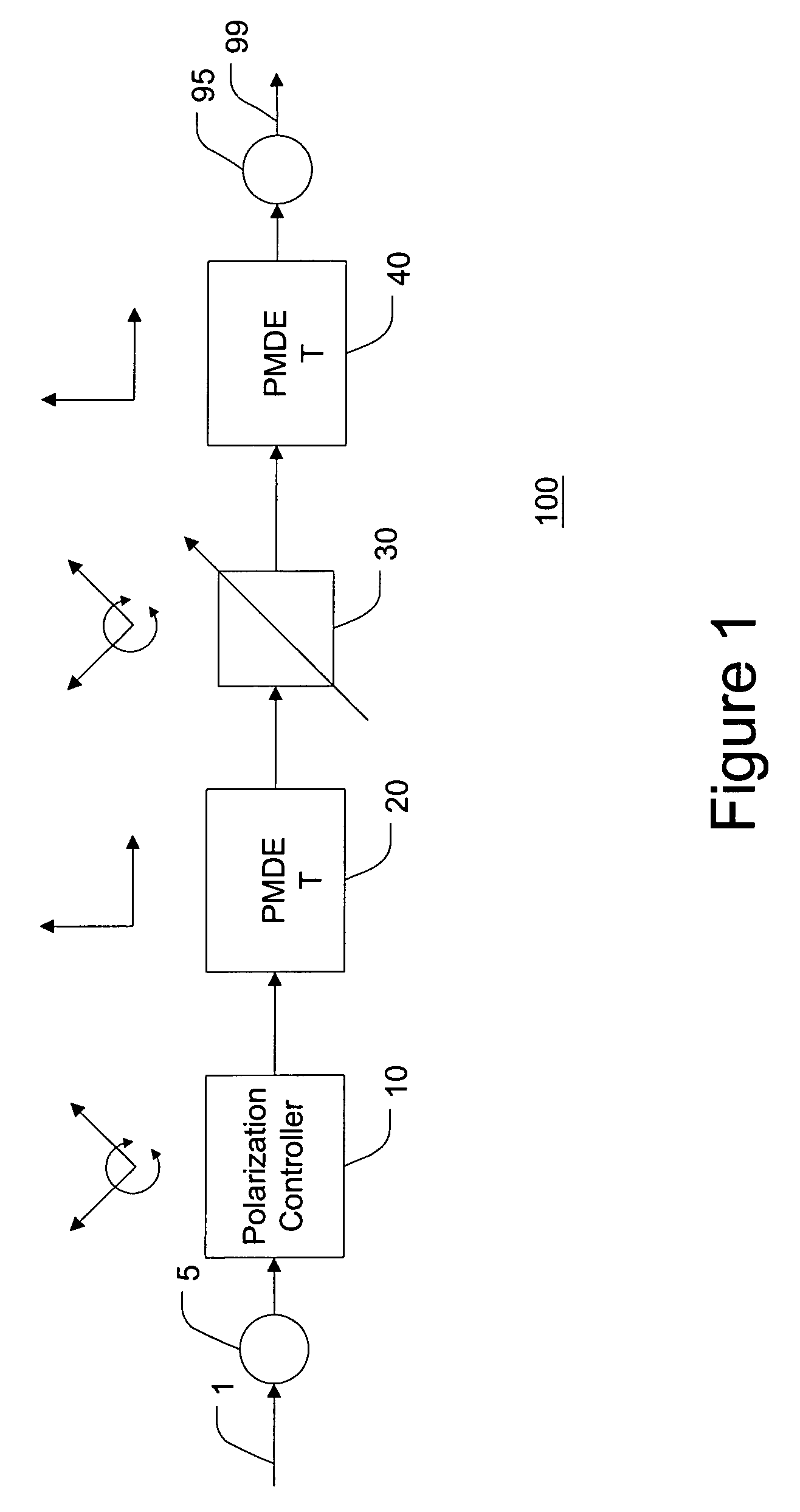
[0033]FIG. 1 illustrates the main components of the polarization compensator 100. An input port 5 receives an input optical signal 1 suffering from PMD. The input port 5 may be, for example, a connector, splice or other connection between the polarization compensator...


PUM


Abstract

Residual birefringence in optical fibers causes polarization mode dispersion (PMD). The invention compensates for this by using a polarization mode dispersion compensator and a polarimeter. The PMD compensator has a variable PMD that may be controlled. The output of the PMD compensator is monitored by a polarimeter. By dithering the wavelength of the optical signal, the polarimeter may provide an accurate measure of the PMD. A controller uses this measurement to control the PMD compensator. The PMD compensating scheme may also be incorporated in a wavelength division multiplexed system with each channel having its own PMD compensator. In addition, a control method may control any polarization mode dispersion compensator based on feedback from a polarimeter to reduce the PMD of the input signal. Instead of using a polarimeter, a Q detector may be used to monitor the output of the PMD compensator. The Q detector provides a measurement of the edge sharpness and, thereby, a measure of the PMD. The controller may use the Q value to control the PMD compensator.

Description

BACKGROUND OF THE INVENTION[0001]1. Field of Invention[0002]The present invention relates to optical communications systems. More particularly, the present invention relates to polarization mode dispersion compensating systems and methods.[0003]2. Description of Related Art[0004]Polarization mode dispersion (PMD) is a well-known problem caused by the undesired, residual birefringent properties of optical fibers. Despite the attempts of optical fiber manufacturers to eliminate PMD, a residual amount of PMD is still present. Moreover, there are a variety of existing fiber plants having fibers not optimized to reduce PMD.[0005]Essentially, PMD causes the two principal states of polarization to propagate along an optical fiber at different rates. The polarization of an optical signal may be expressed in terms of two components (the so-called “principal states of polarization” (POS)). The two principal polarization states each experience different propagation delays as they propagate dow...

Claims


Application Information

Patent Timeline
IPC IPC(8): H04B10/00H04B10/18
CPCH04B10/2569
Inventor TAYLOR, MICHAEL G.
Owner CIENA
Why Eureka
Try Eureka