Frequency converter and radio communication apparatus

a frequency converter and radio communication technology, applied in the direction of transmission, modulation transference by semiconductor devices with minimum 2 electrodes, electrical devices, etc., can solve the problems of poor conversion gain of frequency converters that employ mixers described in the document, and achieve low noise figure and high conversion gain

Inactive Publication Date: 2006-09-12
KK TOSHIBA
View PDF8 Cites 12 Cited by
  • Summary
  • Abstract
  • Description
  • Claims
  • Application Information

AI Technical Summary

Benefits of technology

[0009]It is an object of the present invention to provide a frequency converter and a radio communication apparatus that have high conversion gain and low noise figure.

Problems solved by technology

However, in the frequency converter that employs such mixers, such condition is not met since the driver stage and the switching stage have mainly capacitive load (−JX, where X is a positive number) in a high frequency.
As a result, the frequency converters that employ the mixers described in the document have poor conversion gain.

Method used


Image

  • Frequency converter and radio communication apparatus
  • Frequency converter and radio communication apparatus
  • Frequency converter and radio communication apparatus

Examples


Embodiment Construction

[0023]Exemplary embodiments of the frequency converter and the radio communication apparatus relating to the present invention are explained in detail below with reference to the accompanying drawings.

[0024]The frequency converter relating to the present invention is characterized by comprising an impedance matching unit, in addition to the conventional mixer.

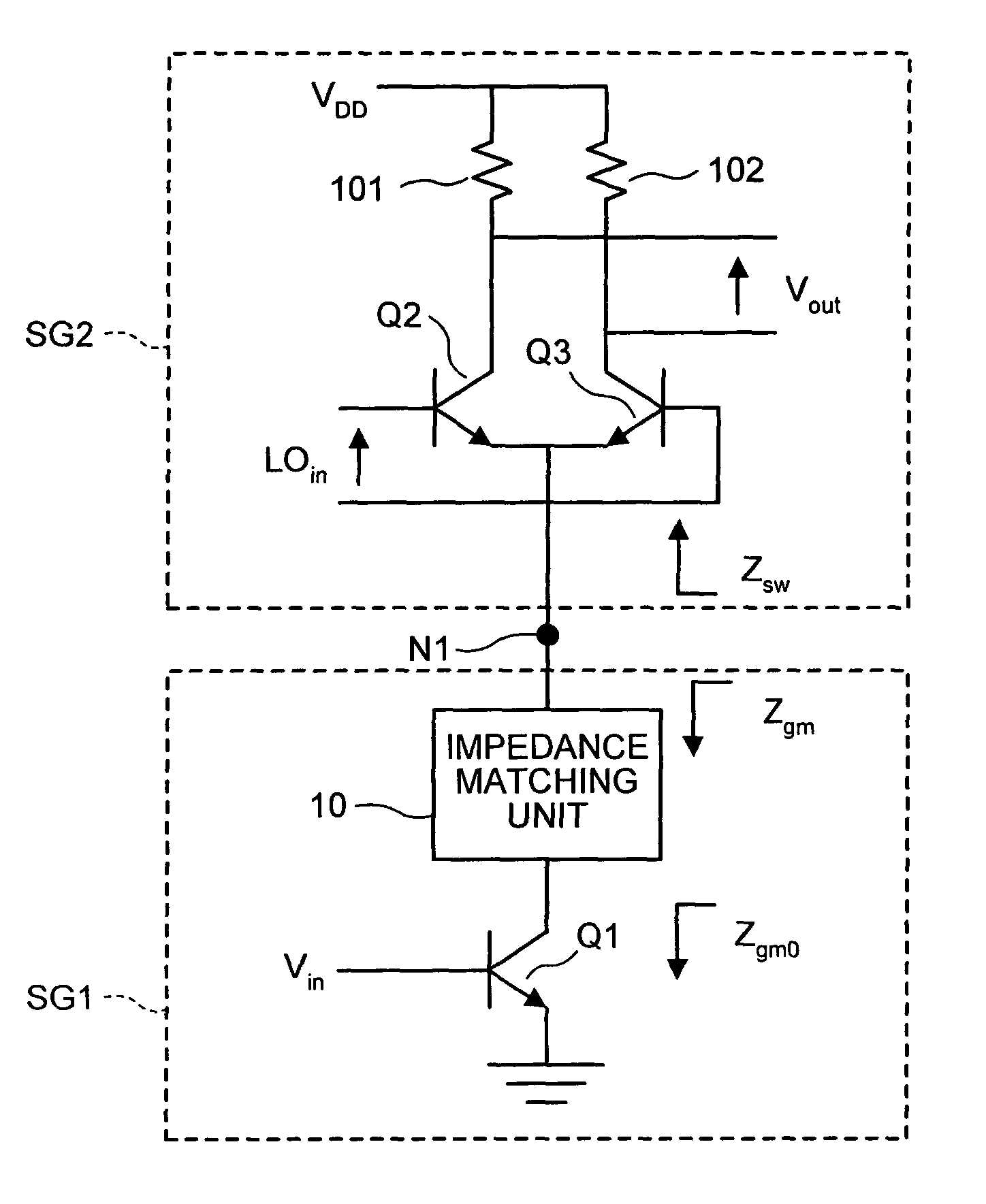
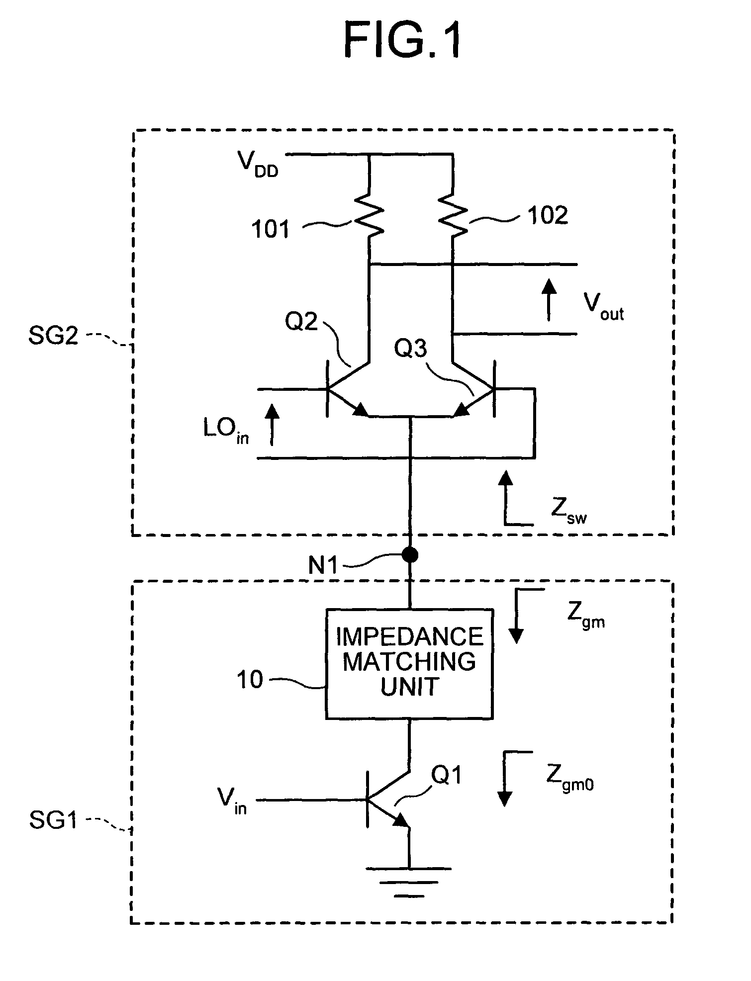
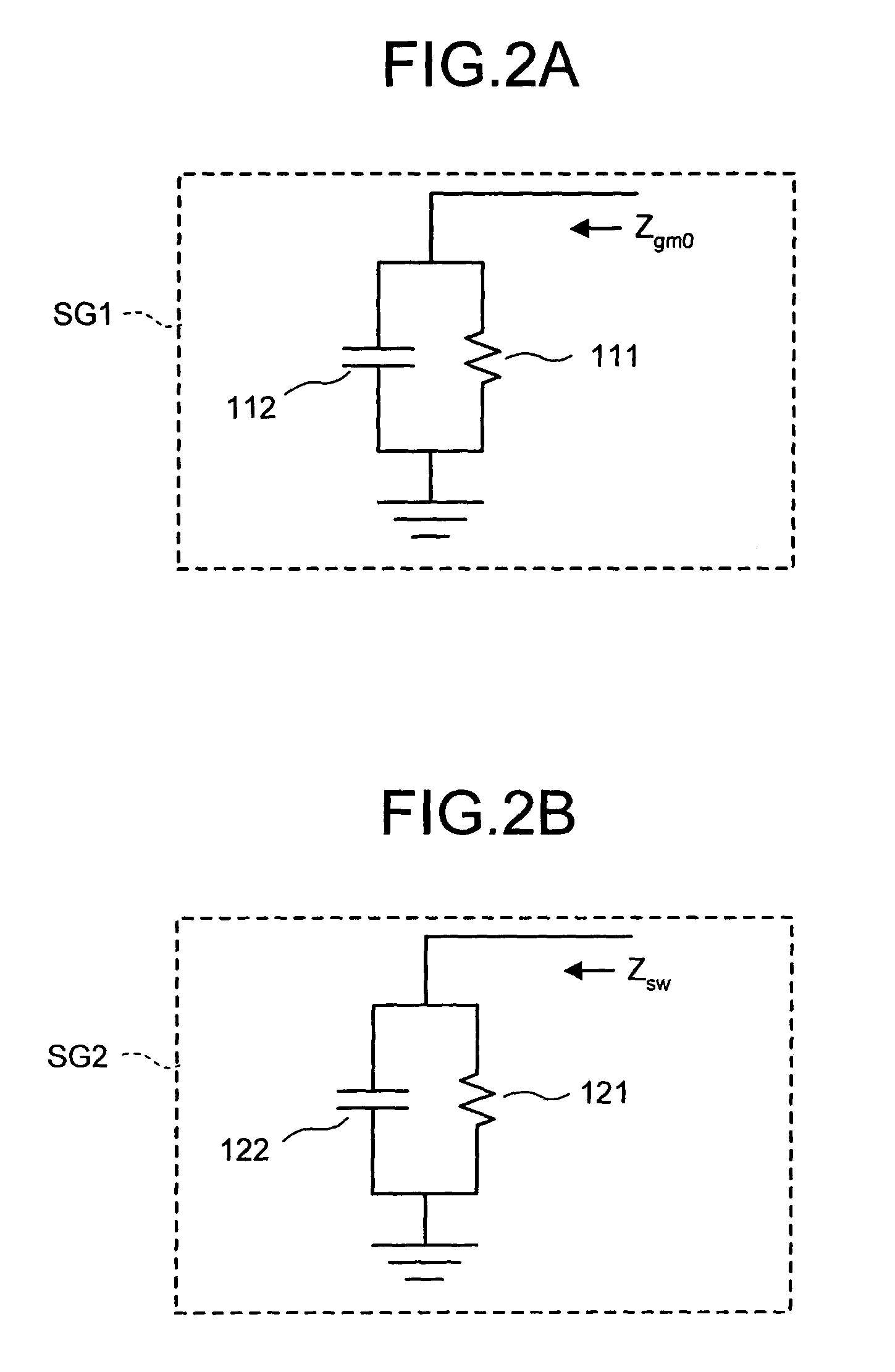
[0025]FIG. 1 is a circuit diagram of the frequency converter according to one embodiment of the present invention. An impedance matching unit 10 is provided in the conventional single balanced mixer. The impedance matching unit 10 is connected between the collector of an NPN transistor Q1 and the emitters (hereinafter, “switch emitter”) of NPN transistors Q2 and Q3. The impedance matching unit 10 has inductive degeneration, and concretely comprises at least one inductor formed as an integrated circuit (IC).

[0026]The frequency converter shown in FIG. 1 may be divided into two stages at the junction (a node N1 in FIG. 1) between ...


PUM


Abstract

A frequency converter comprises an impedance matching unit connected to a current switching stage and a transconductance amplifier stage. The impedance matching unit has an impedance for conjugate power match. For example, the impedance matching unit is a parallel resonant circuit that includes an inductor and a capacitor that are formed as an integrated circuit. Thus, the frequency converter that has high conversion gain and low noise is obtained.

Description

CROSS-REFERENCE TO RELATED APPLICATIONS[0001]This application is based upon and claims the benefit of priority from the prior Japanese Patent Applications No. 2002-280739 filed on Sep. 26, 2002 and No. 2003-152081 filed on May 29, 2003 the entire contents of which are incorporated herein by reference.BACKGROUND OF THE INVENTION[0002]1) Field of the Invention[0003]The present invention relates to an improvement in a frequency converter. This invention also relates to a radio communication apparatus that employs the frequency converter as an up-converter or a down-converter.[0004]2) Description of the Related Art[0005]Information devices, employing radio communications such as mobile phones and portable information devices, have recently attracted increasing research and development. Because of such research and development, the information devices are day-by-day becoming smaller and cheaper.[0006]The information device becomes smaller or cheaper if analog radio frequency (RF) circuit...

Claims


Application Information

Patent Timeline
Patent Type & Authority Patents(United States)
IPC IPC(8): H04B1/26H03D7/12H04B1/40
CPCH04B1/406
Inventor OTAKA, SHOJI
Owner KK TOSHIBA
Why Eureka
Try Eureka