Cable retention device

Inactive Publication Date: 2006-09-19
DT SEARCH & DESIGNS
View PDF19 Cites 22 Cited by
  • Summary
  • Abstract
  • Description
  • Claims
  • Application Information

AI Technical Summary

Benefits of technology

[0010]The present invention overcomes the disadvantages of the prior art by providing a preformed cable tie which has a unique non-binding configuration, which has a partially deformable inner surface and which can be secured with one

Problems solved by technology

The disadvantages of the prior art devices described above are several.
First and foremost, with many types of cable, especially low voltage computer cables, the cable is sensitive to binding and it is frequently the case that the cable tie is tightened too tightly so that it adversely affects the performance of the equipment being fed by the cable.
If an uncoated wire is utilized as the tie, significant damage to the cable or cables being secured may result.
Another disadvantage of the prior art, even when utilizing the more popular plastic cable ties described above, is that there is no way to judge when the tie is properly secured and since there is no margin for error, the tie may be too tight and adversely affect performance without the k

Method used


Image

  • Cable retention device
  • Cable retention device

Examples


Embodiment Construction

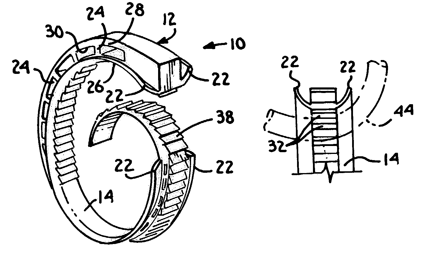
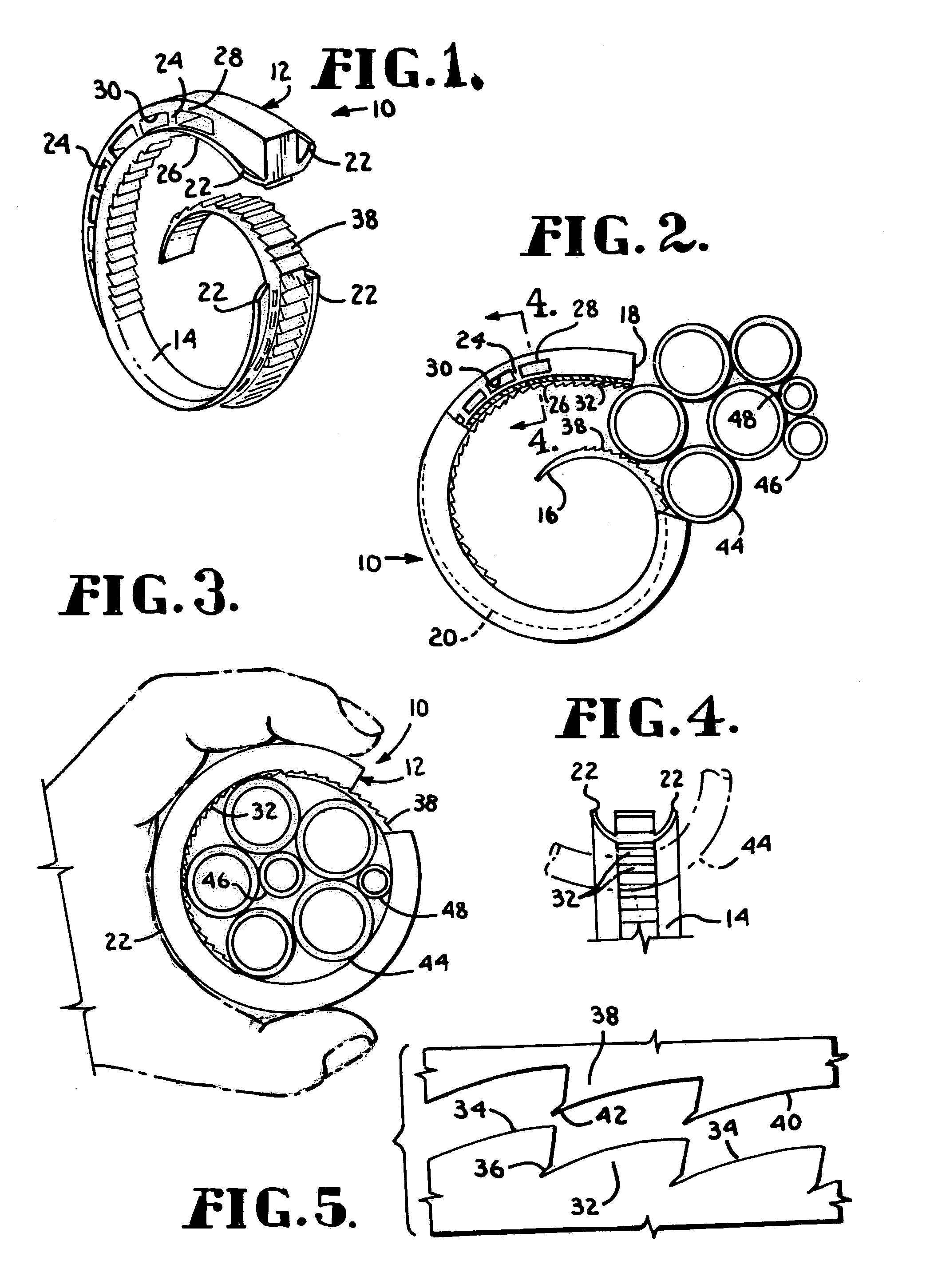
[0028]Referring initially to FIG. 1, the cable tie according to the present invention is designated generally by the numeral 10. Cable tie 10 comprises an annular support 12 of generally rectangular cross section and a generally convex inner face 14 which is integrally formed with annular support 12 around its circumference. The cross sectional area of the support 12 decreases significantly from one end to the other. It is desirable that the cross sectional area of the terminal end designated by the numeral 16 in FIG. 2 be 20 to 25 percent of the area of the opposite terminal end 18 (see FIG. 2). The gradually decreasing dimension of annular support 12 is indicated by broken line 20 in FIG. 2. It is also to be noted that portions of convex inner face 14 are formed by wings 22 which are integral with and project outwardly from support 12.

[0029]The construction of annular support 12 is further defined by a honeycomb structure comprising a plurality of spaced apart cross members 24 and...


PUM


Abstract

A tie for bundling a plurality of elongated objects is formed in a generally arcuate configuration from a material having shape retaining memory properties. Complemental teeth on two opposed surface lock the two surfaces together to form a closed loop.

Description

CROSS-REFERENCE TO RELATED APPLICATIONS[0001]This application is based on U.S. Provisional Application Ser. No. 60 / 355,430, filed on Feb. 8, 2002, which is hereby incorporated herein by reference.STATEMENT REGARDING FEDERALLY SPONSORED RESEARCH OR DEVELOPMENT[0002]Not Applicable.BACKGROUND OF THE INVENTION[0003]This invention relates generally to restraining devices and, more particularly to a tie for securing one or more same diameter objects such as cables or wires in a bundle or to another object.[0004]Existing cable ties take several forms. The most elementary example is a wile which is either bare or is coated with insulation and which is twisted around one or more cables which it is desired to bundle together. A more popular cable tie which is now used is a preformed plastic strip which has teeth which pass through a catch box where the teeth engage a complemental restraint which locks the end of the tie in place.[0005]The disadvantages of the prior art devices described above...

Claims


Application Information

Patent Timeline
IPC IPC(8): B65D63/10H02G3/30
CPCH02G3/30Y10T24/142Y10T24/44248Y10T24/153Y10T24/1498
Inventor THOMPSON, ALVIN DEAN
Owner DT SEARCH & DESIGNS
Why Eureka
Try Eureka