Secondary air supplying apparatus

a technology of secondary air and air supply, which is applied in the direction of domestic cooling apparatus, lighting and heating apparatus, electric control, etc., can solve the problems of catalyst overheating, damage, and increase the temperature of the catalyst faster, and achieve the effect of suppressing the catalyst overheating

Active Publication Date: 2006-09-19
TOYOTA JIDOSHA KK
View PDF6 Cites 3 Cited by
  • Summary
  • Abstract
  • Description
  • Claims
  • Application Information

AI Technical Summary

Benefits of technology

[0007]An object of the present invention is to provide a secondary air supplying apparatus capable of implementing appropriate activation of the catalyst while suppressing the overheating of the catalyst even when the coolant temperature is relatively low.
[0013]Preferably, the summing means stores the sum if the engine is stopped during the actuation of the secondary air supplying means. Where the engine is stopped during the supply operation, storing the sum shortens the actuation period of the secondary air supplying apparatus at a next start, which can avoid oversupply of secondary air and shorten the actuation period of the air pump. In this case, preferably, the summing means does not reset the stored sum but continues summing, even if the difference between the coolant temperature and the intake air temperature is not more than the first predetermined value, after a restart of the internal combustion engine.
[0014]Preferably, the supply controlling means measures an on-duration of the secondary air supply by the secondary air supplying means and, if the duration reaches a predetermined upper limit, the supply controlling means stops the secondary air supply by the secondary air supplying means. This enables the apparatus to achieve optimal activation through the use of the sum based on the coolant temperature and the intake air temperature and to suppress the oversupply of secondary supply air more effectively.
[0015]Preferably, the supply controlling means measures an amount of the secondary air supply by the secondary air supplying means and, when the amount of the secondary air supply reaches a predetermined upper limit, the supply controlling means stops the secondary air supply by the secondary air supplying means. This enables the apparatus to achieve optimal activation through the use of the sum based on the coolant temperature and the intake air temperature and to suppress the oversupply of secondary supply air more effectively.

Problems solved by technology

However, there are cases where an increase speed of the catalyst temperature is faster than an increase speed of the coolant temperature and where the catalyst has been already activated even at relatively low coolant temperatures.
In such cases, where the actuation period of the secondary air supply system is too long, there are possibilities of causing overheating of the catalyst and damage due to continuous operation of the air pump.

Method used


Image

  • Secondary air supplying apparatus
  • Secondary air supplying apparatus
  • Secondary air supplying apparatus

Examples


first embodiment

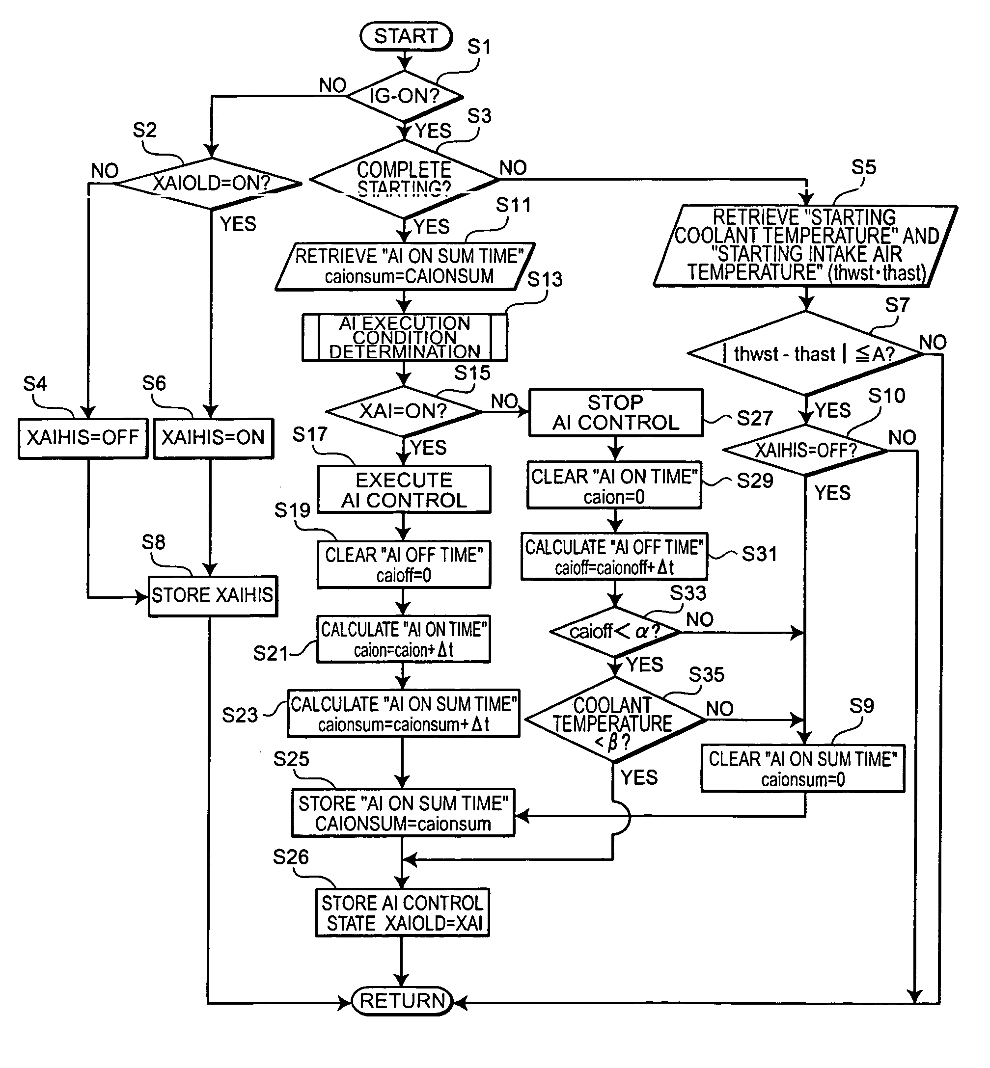
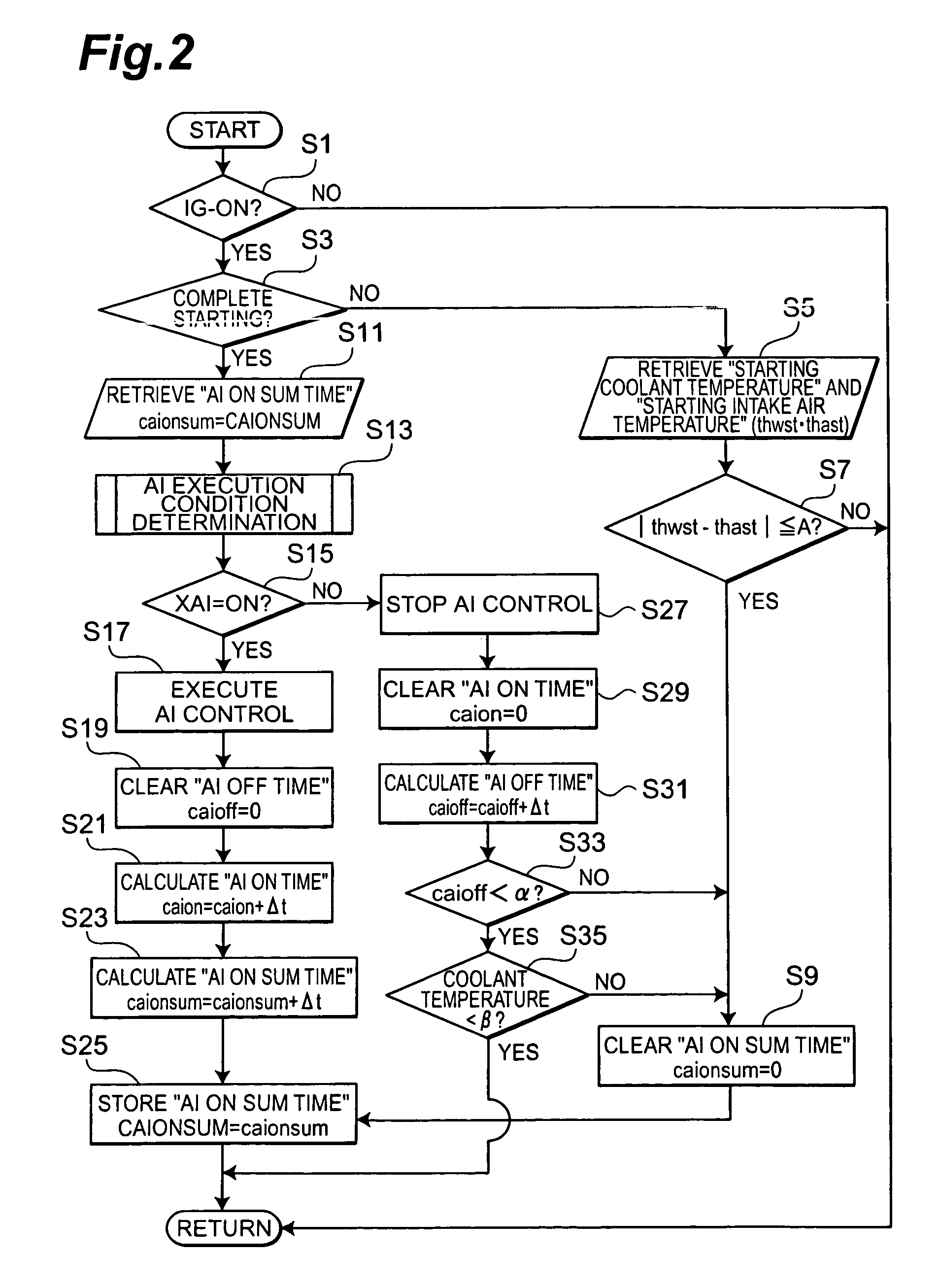
[0028]FIGS. 2 and 3 are flowcharts showing the control. FIG. 2 is a flowchart of the main processing thereof. FIG. 3 is a flowchart showing an AI execution condition determining process in the main processing. The main processing of FIG. 2 is repeatedly executed at predetermined timings between an on time and an off time of power of a vehicle by the controller 1 in collaboration with the engine ECU 23. The process of FIG. 3 is called from the processing of FIG. 2 and then executed.

[0029]At the first step, it is determined whether the ignition (IG) switch of the vehicle is ON (step S1). When the IG switch is OFF, the processes thereafter are skipped to terminate the processing. When the IG switch is ON, it is then determined whether or not a starting of the engine 2 is completed (step S3).

[0030]When the starting is not completed, the controller moves to step S5 to retrieve a starting coolant temperature thwst measured by coolant temperature sensor 28 and a starting air temperature th...

second embodiment

[0048]FIG. 5 is a timing chart showing an example of time changes of engine start states, AI control flag XAI, AI state history XAIHIS, AI on time caion, AI on sum time CAIONSUM, coolant temperature, and intake air temperature in the case of the second embodiment being executed.

[0049]In the present embodiment, as shown in the figure, the value of the AI on sum time CAIONSUM is stored if the engine is stopped during the AI operation (times t1–t2) or if the difference between coolant temperature and intake air temperature is not less than the predetermined temperature (times t3–t4). In an AI operation thereafter, the summing operation is carried out from the stored value, so as to prevent the AI on-duration from becoming long during intermittent AI operation. This can prevent the damage of AP 12.

[0050]In the forms herein the coolant temperature was compared with the threshold β at step S35. However, another conceivable configuration is such that at step S35 the difference between cool...


PUM


Abstract

A secondary air supplying apparatus of the present invention comprises a secondary air supplying device for supplying secondary air to upstream of an emission purifying device in an exhaust system of an internal combustion engine, a coolant temperature sensor for detecting a temperature of a coolant for the engine, an intake air temperature sensor for detecting a temperature of intake air, a supply controller for actuating the secondary air supplying device in accordance with a predetermined secondary air supply condition, and a summing unit for summing an actuation period of the secondary air supplying device and storing a sum. The supply controller stops the secondary air supply by the secondary air supplying device when the sum stored by the summing unit reaches a predetermined upper limit. The summing unit resets the stored sum, if a difference between the coolant temperature and the intake air temperature at a point before the actuation of the secondary air supplying device is not more than a predetermined value. This configuration enables the apparatus to suppress oversupply of secondary air and overheating of a catalyst so as to implement appropriate activation of the catalyst.

Description

BACKGROUND OF THE INVENTION[0001]1. Field of the Invention[0002]The present invention relates to secondary air supplying apparatuses for supplying secondary air to upstream of an emission purifying device of an internal combustion engine.[0003]2. Related Background Art[0004]An example of the known emission control systems of internal combustion engine is an apparatus with a three way catalyst in the exhaust system to reduce CO, HC, and NOx components in exhaust gas and thereby clean up exhaust emissions. Furthermore, there is a known technique of connecting a secondary air supply path equipped with a switching valve, to an exhaust manifold, and pressure-feeding air (secondary air) into the exhaust manifold by means of an air pump to increase the oxygen content in exhaust, thereby effecting the cleanup based on promotion of oxidation of HC and CO in exhaust (Japanese Patent Application Laid-Open No. 2000-240434: [0018]–[0030], FIGS. 3, 7–9).[0005]The technology described in the above...

Claims


Application Information

Patent Timeline
Patent Type & Authority Patents(United States)
IPC IPC(8): F01N3/00F01P7/02F02D41/00F25D17/00F01N3/22F01N3/32
CPCF01N3/22
Inventor HIROOKA, SHIGEMASA
Owner TOYOTA JIDOSHA KK
Why Eureka
Try Eureka