Tool with integral fluid reservoir for handling oil and fuel filters

Inactive Publication Date: 2006-09-19
JERANTOWSKI STANLEY
View PDF7 Cites 18 Cited by
  • Summary
  • Abstract
  • Description
  • Claims
  • Application Information

AI Technical Summary

Benefits of technology

[0008]It is a further object of this invention to provide a tool that allows fuel and oil filters to be changed much more quickly, securely and cleanly than has heretofore been possible.
[0009]It is a further object of this invention to provide a tool that allows the user to remove and install an oil or fuel filter without a serious risk of burning his or her hands.
[0010]It is a further object of this invention to provide a tool with an integral reservoir for trapping fluids that drain from a vehicle using the filter so that environmental pollution is reduced.
[0011]It is a further object of this invention to provide a tool that is able to effectively grip, turn and hold virtually all sizes of fuel and oil filters and which provides a reservoir for all such filters so that leaking or dripping fuel or oil is effectively collected.
[0012]This invention results from a realization that standard filter wrenches may be improved upon significantly by a filter handling tool utilizing an integral fluid reservoir that traps and collects oil, gasoline and other fluids that drain from an engine when the filter is removed by the tool. This invention results from the further realization that such a tool may be constructed efficiently to fit virtually all sizes of filters by employing a unique tapered filter gripping structure within the tool.
[0013]This invention features a tool for use in combination with a fuel or oil filter of the type employed in a motorized land vehicle or marine vessel. The tool includes a generally cylindrical body having an open upper end and a closed lower end. The body includes an interior chamber that carries a plurality of t

Problems solved by technology

Removing a hot oil filter can be an especially messy and hazardous task.
As the filter is removed, engine oil tends to leak onto and coat the exterior of the filter.
This makes the filter extremely messy and slippery to handle.
A person using his or her bare hands may find it difficult to quickly and firmly remove or reattach the filter.
The outer wall of the filter also tends to be extremely hot and can cause a serious burn if it is handled directly.
In addition to the foregoing problems, a previously installed filter is often secured tightly to the engine

Method used


Image

  • Tool with integral fluid reservoir for handling oil and fuel filters
  • Tool with integral fluid reservoir for handling oil and fuel filters
  • Tool with integral fluid reservoir for handling oil and fuel filters

Examples


Embodiment Construction

[0016]Other objects, features and advantages will occur from the following description of a preferred embodiment and the accompanying drawings, in which:

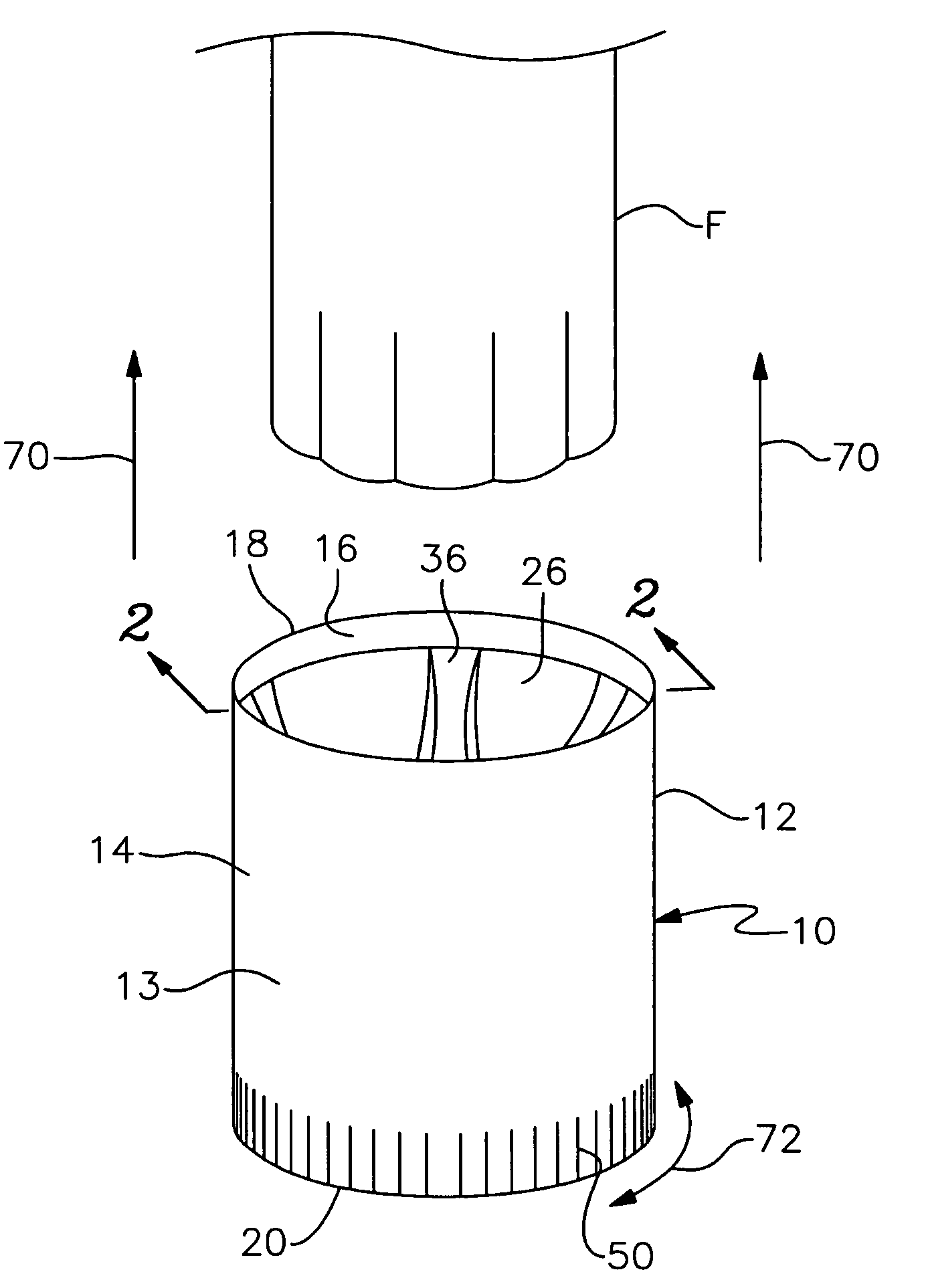
[0017]FIG. 1 is a perspective view of a preferred version of the filter tool of this invention positioned next to an oil or fuel filter of a land vehicle or marine vessel,

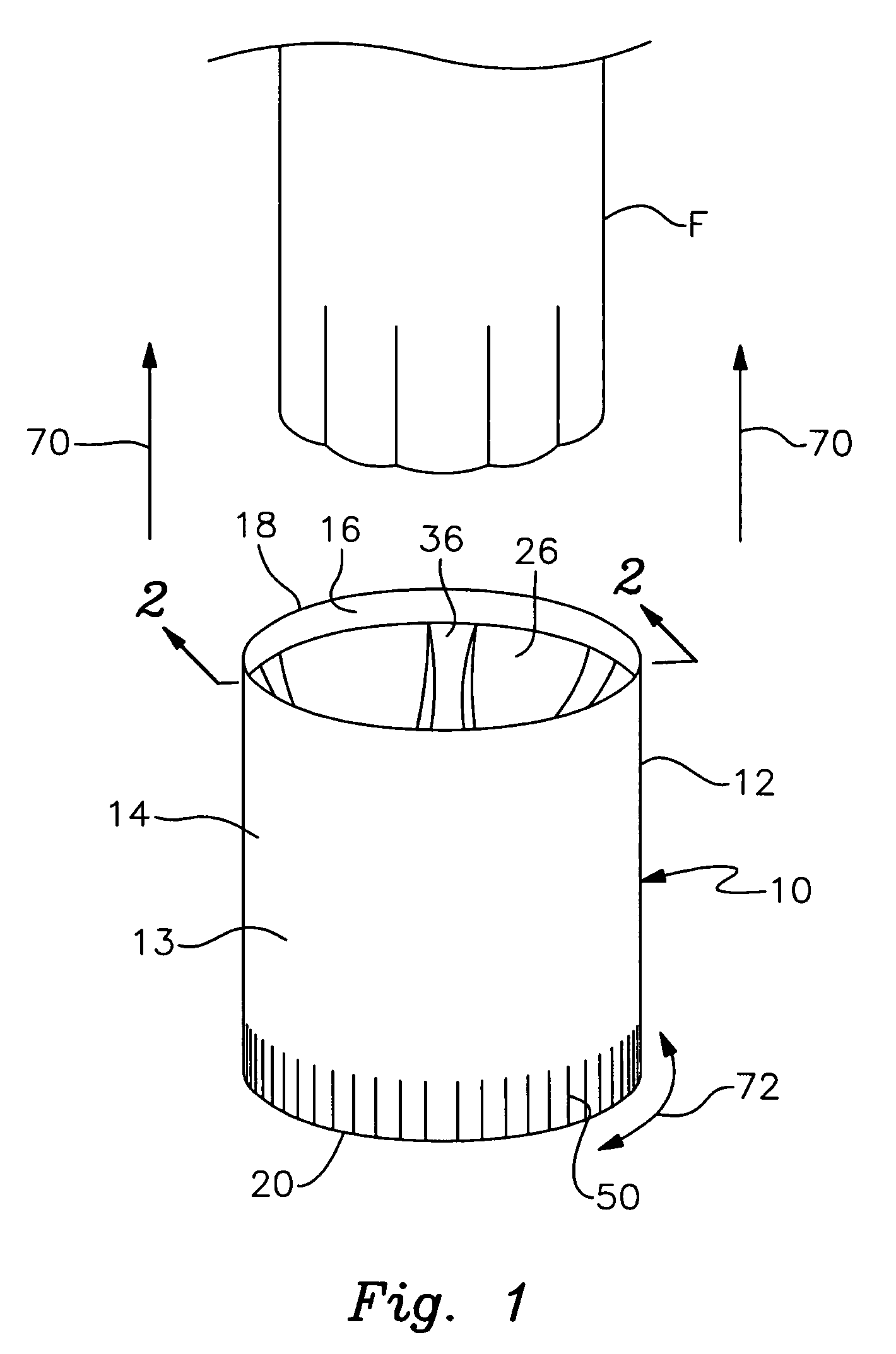
[0018]FIG. 2 is a cross sectional view taken along line 2—2 of FIG. 1;

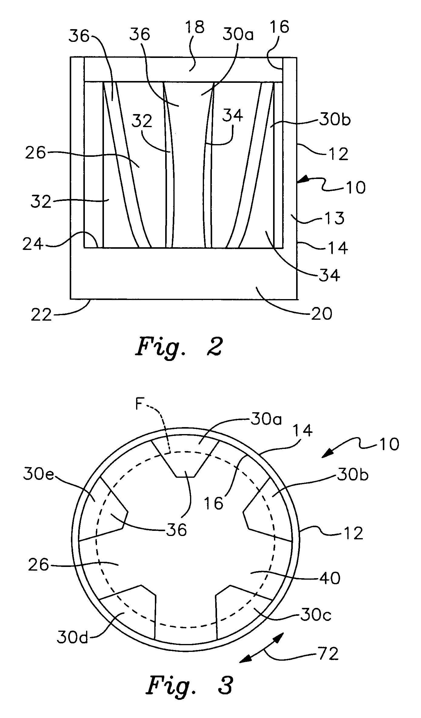
[0019]FIG. 3 is a top plan view of the filter tool with a fuel or oil filter shown in phantom within the interior chamber of the wrench and engaged by the radially inward fingers; and

[0020]FIG. 4 is an elevational, cross sectional view similar to FIG. 2 with a filter positioned within the tool and engaged by the gripping projections of the wrench; and

[0021]FIGS. 5, 6 and 7 are top, cross sectional side and bottom views respectively of an alternative preferred tool according to this invention.

[0022]There is shown in FIG. 1 a filter handling tool 10 that is designed to be used in connection with va...


PUM


Abstract

A tool for oil and fuel filters includes a generally cylindrical body having an open upper and a closed lower end. The body includes an interior chamber having a plurality of tapered radial projections that extend longitudinally within the interior chamber. The projections include respective tapered gripping surfaces that engage filters having respective diameters at corresponding depths within the chamber. The chamber defines a reservoir for collecting fluid that leaks when the filter is removed.

Description

RELATED APPLICATION[0001]This application claims the benefit of U.S. Provisional Patent Application Ser. No. 60 / 498,330 filed Aug. 26, 2003.FIELD OF THE INVENTION[0002]This invention relates to a tool designed for removing and installing oil and fuel filters of the type used in land vehicles and marine vessels. More particularly, this invention relates to a filter handling tool having an integral reservoir for collecting fluid (e.g. oil, gasoline or diesel fuel) that drains when the filter is removed.BACKGROUND OF THE INVENTION[0003]Virtually all motorized land vehicles and marine vessels employ fuel and oil filters. Periodically, these components require removal and replacement. Removing a hot oil filter can be an especially messy and hazardous task. As the filter is removed, engine oil tends to leak onto and coat the exterior of the filter. This makes the filter extremely messy and slippery to handle. A person using his or her bare hands may find it difficult to quickly and firmly...

Claims


Application Information

Patent Timeline
IPC IPC(8): B24B13/06
CPCB25B27/0042B01D2201/24
Inventor JERANTOWSKI, STANLEY
Owner JERANTOWSKI STANLEY
Why Eureka
Try Eureka