Exhaust gas control device for internal combustion engines

a control device and internal combustion engine technology, applied in the direction of machines/engines, mechanical equipment, separation processes, etc., can solve the problems of exhaust gas discharge to the atmosphere, undesired engine corrosion and oil degradation, and increased volume of discharged sooty smoke and noxious gas included in the exhaust gas, so as to reduce the volume of unburned fuel and minimize environmental pollution

Inactive Publication Date: 2006-03-07
LEE JU CHEOL
View PDF9 Cites 35 Cited by
  • Summary
  • Abstract
  • Description
  • Claims
  • Application Information

AI Technical Summary

Benefits of technology

[0009]Accordingly, the present invention has been made keeping in mind the above problems occurring in the prior art, and an object of the present invention is to provide an exhaust gas control device for internal combustion engines, which not only reduces the volume of unburnt fuel discharged to the atmosphere during an operation of an engine, but also inhibits noxious materials contained in the exhaust gas from being discharged to the atmosphere, thereby minimizing environmental pollution.

Problems solved by technology

However, the main noxious components that may cause environmental pollution are the NOx, CO and HC.
The corrosion of the engine and the degradation of oil are undesirably caused when the blowby gas is left in the crank case.
However, when using this configuration, the content of the noxious HC in the discharged blowby gas is undesirably high, and thus it is necessary to discharge the blowby gas to the atmosphere after reburning the blowby gas.
When the exhaust gas is directly discharged to the atmosphere through an exhaust pipe, the volume of discharged sooty smoke and noxious gas is relatively small when the engine is driven at low speeds under 1,500 RPM, whereas the volume of the discharged exhaust gas is increased at high speeds above 1,500 RPM, so the volume of the discharged sooty smoke and noxious gas included in the exhaust gas is undesirably increased, with the sooty smoke and noxious gas being the principal cause of air pollution.
The exhaust gas discharged to the atmosphere is problematic in that a variety of noxious components of the exhaust gas including carbon monoxide, hydrocarbon, sulfur, nitrous oxide, aldehyde and suspended particles, are discharged to the atmosphere.
A diesel engine has a problem that it does not use a catalytic converter at the exhaust pipe, so the non-purified exhaust gas is directly discharged to the atmosphere and causes air pollution.

Method used


Image

  • Exhaust gas control device for internal combustion engines
  • Exhaust gas control device for internal combustion engines
  • Exhaust gas control device for internal combustion engines

Examples


first embodiment

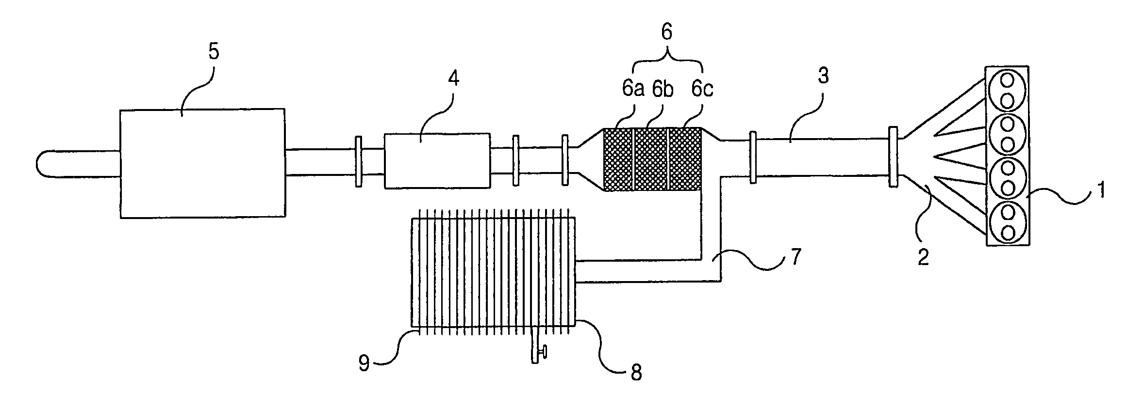
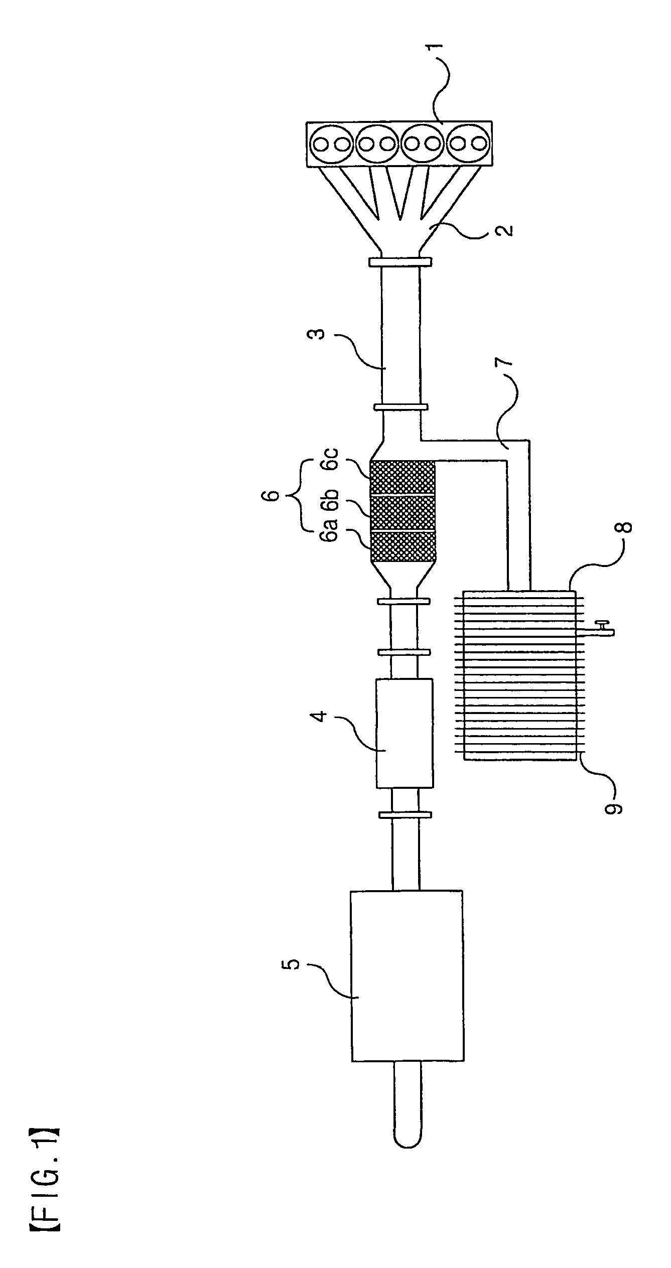
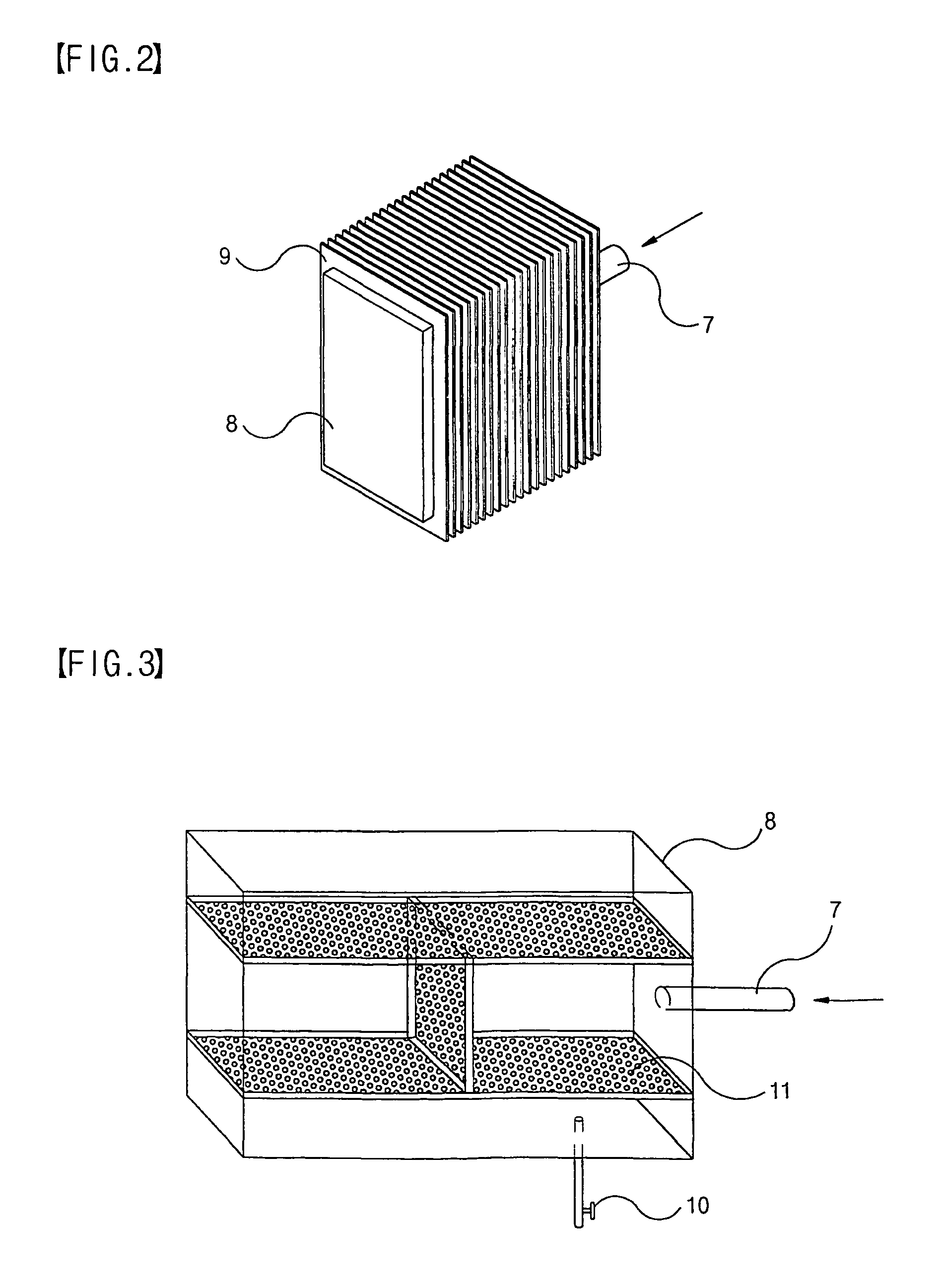
[0019]FIGS. 1 to 3 illustrate the construction of an exhaust gas control device according to the present invention.

[0020]As shown in the drawings, the exhaust gas control device for internal combustion engines comprises a combustion chamber 1 of an engine, an exhaust manifold 2, a main exhaust pipe 3 provided with a plurality of mufflers 4, 5 and with a catalytic converter 6 having a plurality of sequentially arranged catalyst units 6a, 6b and 6c, and an unburnt fuel collection tank 8 connected to the catalytic converter 6 through a branch pipe 7 for collecting purified unburnt fuel after the unburnt fuel is treated by the catalytic converter 6 so as to remove noxious materials therefrom. In the catalytic converter 6, the perforations of the catalyst units 6a, 6b and 6c are gradually reduced in their sizes.

[0021]Referring to FIG. 2, the unburnt fuel collection tank 8 is provided with a plurality of cooling fins 9 for reducing the temperature of the inside of the main exhaust pipe 3,...

second embodiment

[0034]FIGS. 4 to 6 illustrate the exhaust gas control device according to the present invention, which includes a return channel.

[0035]In FIG. 4 showing the overall construction of the exhaust gas control device, the combustion chamber 1 is provided on its one end with an intake manifold 22 connected to an air cleaner 21, and on its opposite end with an exhaust manifold 2. A main exhaust pipe 3 communicating with the exhaust manifold 2 comprises a catalytic converter 6, a branch pipe 7 and an unburnt fuel collection tank 8, similarly to the Construction of the first embodiment.

[0036]According to the second embodiment of the present invention, the main exhaust pipe 3 is additionally provided with a return channel, so the exhaust gas is repeatedly guided to the intake manifold 22.

[0037]The return channel is comprised of a water-cooled cooling unit 25 for primarily cooling the high temperature exhaust gas by using refrigerant, an air-cooled cooling unit 26 for additionally cooling the ...


PUM


Abstract

Disclosed herein is an exhaust gas control device for internal combustion engines. The exhaust gas control device has a main exhaust pipe (3) communicating with an exhaust manifold (2) used for guiding exhaust gas discharged from a combustion chamber (1) of an engine, a catalytic converter (6) arranged on a predetermined position of the main exhaust pipe (3) for purifying unburnt fuel discharged with the exhaust has and having a plurality of sequentially arranged catalyst units (6a, 6b, 6c), and an unburnt fuel collection tank (8) provided with a plurality of cooling fins (9) and connected to the catalytic converter (6) through a branch pipe (7). The collection tank (8) collects purified unburnt fuel after the unburnt fuel is treated by the catalytic converter (6) so as to remove noxious materials therefrom.

Description

TECHNICAL FIELD[0001]The present invention relates generally to an exhaust gas control device for internal combustion engines, and more particularly, to an exhaust gas control device for internal combustion engines, which collects unburnt fuel that may cause environmental pollution when it is discharged with exhaust gas from a combustion chamber of an engine during an operation of the engine, thereby preventing environmental pollution caused by the release of the noxious unburnt liquid materials.BACKGROUND ART[0002]Generally, gases generated from vehicles are classified into three types according to gas sources, that is, exhaust gas from an exhaust pipe, blowby gas generated from the crank case of an engine, and evaporation gas from a fuel tank or a vaporizer.[0003]Of the gases from vehicles, the exhaust gas is discharged to the atmosphere from the exhaust pipe after fuel is burnt in an engine cylinder, and has a complicated composition consisting of noxious gas components and harml...

Claims


Application Information

Patent Timeline
Patent Type & Authority Patents(United States)
IPC IPC(8): F01N5/00B01D53/86F01N3/00F01N3/02F01N3/038F01N3/04F01N3/05F01N3/28F01N13/02F02M25/07
CPCB01D53/864F01N13/0093F01N3/02F01N3/038F01N3/043F01N3/05F01N3/28F01N3/2882F01N13/02F02M25/0731F02M25/074F01N13/0097F01N3/005F01N3/2803F01N2240/02F01N2250/02F01N2250/10F01N2260/022F01N2260/024F02M25/0718F02M25/0742F02M25/0751F02M25/0796Y02T10/121Y02T10/20F02M26/15F02M26/28F02M26/35F02M26/36F02M26/44F02M26/71Y02T10/12
Inventor LEE, JU-CHEOL
Owner LEE JU CHEOL
Why Eureka
Try Eureka