Manhole insert for manufacture of a cast member and to provide a step insert having increased structural and holding strength

a technology of manhole insert and cast member, which is applied in the direction of manufacturing tools, threaded fasteners, screwdrivers, etc., can solve the problems of pin failure, mechanism damage, and seepage through the larger width slots, so as to prevent the seepage of cast material and increase the frictional holding force

Inactive Publication Date: 2006-09-19
POLY TEC PROD
View PDF35 Cites 29 Cited by
  • Summary
  • Abstract
  • Description
  • Claims
  • Application Information

AI Technical Summary

Benefits of technology

[0034]It is still another object of the present invention to provide a novel insert for cast members produced employing the wetcast method and which is adapted to receive the insertable leg of a step having a circular cross-section.
[0035]Still another object of the present invention is to provide a novel insert for use in a drycast method and which is designed to prevent seepage of the cast material into the mechanism of the mold assembly.
[0036]Still another object of the present invention is to provide a novel step for use in a wetcast method wherein the insert is keyed to a insertion pin to assure proper mounting and alignment thereof.
[0037]Still another object of the present invention is to provide a novel insert f...

Problems solved by technology

The insert 10 design shown in FIGS. 1a–1c has a disadvantage that seepage occurs through the larger width slots 15b, 16b provided in the blank 14 while the concrete is being poured into the mold assembly.
Additional problems occurred when the cured concrete parts stripped out of forms were found to exhibit a honeycomb structure in the region where the fines bled through.
In the conventional technique, the tremendous pressures developed within the casting material cause these openings to “sag” or become “off-round” wh...

Method used


Image

  • Manhole insert for manufacture of a cast member and to provide a step insert having increased structural and holding strength
  • Manhole insert for manufacture of a cast member and to provide a step insert having increased structural and holding strength
  • Manhole insert for manufacture of a cast member and to provide a step insert having increased structural and holding strength

Examples


embodiment 30

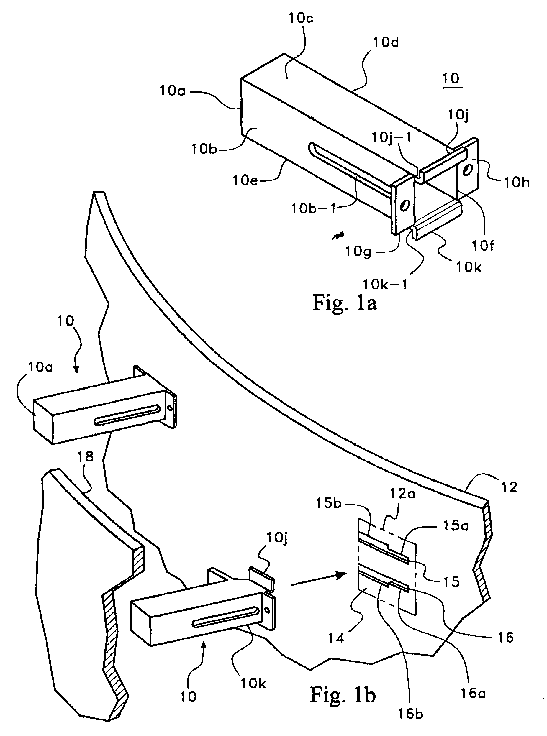
[0058]FIGS. 4a, 4b and 4c show still another embodiment 30 for slidable mounting to a mold member and utilized as a support for wire hoops employed in cast members to enhance structural strength of the cast member and functioning in the same manner as the embodiments described in detail in co-pending application Ser. No. 08 / 853,515 filed May 9, 1997 and incorporated herein by reference thereto.

[0059]The support 30 has a main body portion 31 which is wider at its left-hand end and tapers to a narrow right-hand end 31a. A lower reinforcement flange 32 is integrally joined to the lower en of main body portion 31 forming a substantially inverted T-shaped configuration. A left-hand end reinforcement flange 33 is integrally joined to the left-hand end of main body portion 31 forming a substantially T-shaped cross section as shown best in FIG. 3a.

[0060]The top end of main body portion 31 is joined to an integral upper reinforcement flange 34 forming a substantially T-shaped cross section ...

embodiment 70

[0097]The two-piece insert assembly embodiment 70, shown in FIG. 9 is comprised of first and second hollow, cylindrical-shaped, molded, plastic members 72 and 74. Member 72 has open ends 72a and 72b. A flange 72c provided intermediate ends 72a and 72b lies in a plane which is diagonally aligned relative to the central axis CL. Two (2) slots 72d are arranged at 180 degree intervals about the end 72b of member 72 and extend inwardly from end 72b toward flange 72c. Another set of two (2) slots 72e are arranged at 90 degree intervals about the end 72a of member 72 and extend inwardly from end 72a toward flange 72c. However, the inward end of slots 72e terminate a spaced distance from flange 72c. If desired, the number of slots 72d, 72e may be three or even four or more slots arranged a egui-spaced intervals about the circumference of member 72.

[0098]The major portion of member 72 extending between and 72a and flange 72c has a plurality of individual annular flanges F′, similar to the fl...
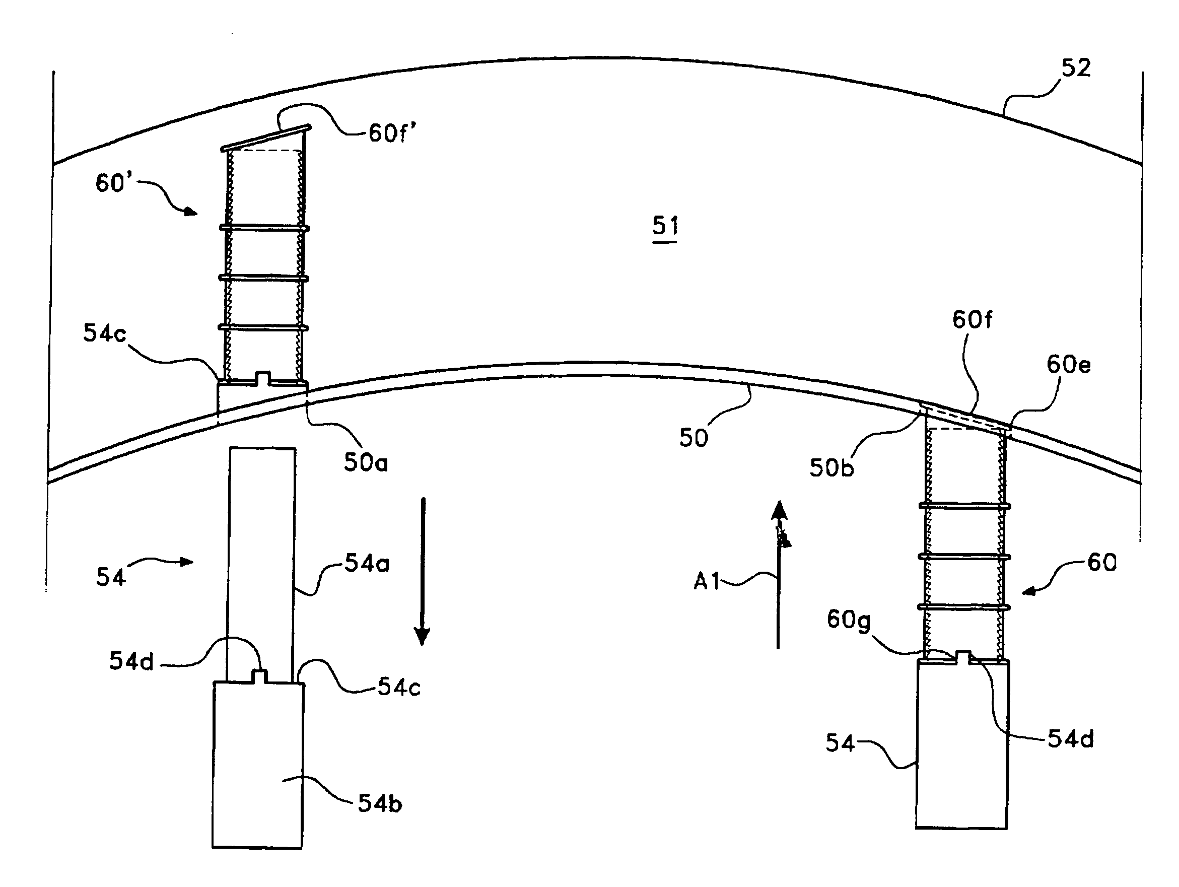
embodiment 60

[0099]Insert member 74 had a closed end 74a and an open end 74b. End 74a has a planar surface which is diagonally aligned relative to center line CL and terminates in an integral annular flange, similar to the embodiment 60 shown in FIG. 6. The exterior of member 74 is further provided with a plurality of integral flanges 74c and 74c′, all of which are planar and lie in planes forming right-angles with the center line CL.

[0100]The interior periphery of member 74 is provided with a plurality of inwardly directed, annular flanges F″, having an inclined surface F1″ which is inclined at an angle to the longitudinal center-line CL and a surface F2″ which is substantially perpendicular to the center-line CL and which is on the side of the flange remote from the end 74b. This design is such as to make it easier for insertion of the end 72a into insert member 74, whereas any effort or attempt to pull the insert member 74 out of insert member 72 is met with an increased frictional holding fo...


PUM

PropertyMeasurementUnit
Thicknessaaaaaaaaaa
Forceaaaaaaaaaa
Widthaaaaaaaaaa

Abstract

Method and apparatus for forming cast members. Steps are provided in the cast member by sliding mounting flanges of hollow plastic step inserts into slots provided in the inner mold shell. The cast material is then poured into the mold. Once the cast material has set, the cast member is withdrawn from the mold assembly. The step insert mounting flanges are broken away, leaving hollow step inserts into which manhole steps are force-fittingly mounted. The inserts are provided with integral cover tabs which cover larger slots provided to facilitate insertion of the step inserts, preventing leakage of the cast material into the mold assembly. Integral cover tabs are similarly provided on enforcement ring support members mounted in a similar fashion to insertion slots provided on one of the mold members to cover larger width slot portions to prevent seepage of cast material. Similar seals are provided by cylindrical-shaped inserts for use in wetcast and drycast fabrication methods.

Description

CROSS REFERENCE TO RELATED APPLICATIONS[0001]This application claims priority from Application No. 60 / 100,234; filed on Sep. 14, 1998 which application is incorporated herein by reference.FIELD OF THE INVENTION[0002]The present invention relates to method and apparatus for producing cast concrete members and the like and more particularly to a method and apparatus for producing cast members in which members utilized to form step inserts and / or to support reinforcement members are provided with means to prevent undesirable seepage of the cast material and thereby retain the cast material into the mold assemblies within the mold assembly as the cast material sets.BACKGROUND OF THE INVENTION[0003]It is well known in the art to provide manhole assemblies with steps to facilitate a descent into and ascent from the manhole assembly through the top opening thereof.[0004]One of the preferred techniques is described, for example, in U.S. Pat. No. 3,974,615 issued Aug. 17, 1976, assigned to t...

Claims


Application Information

Patent Timeline
IPC IPC(8): E06C9/02E06C9/04B28B21/56B28B23/00E04B1/41E04G15/06E04G21/18
CPCB28B21/56B28B23/0056E06C9/04E04G15/063E04G21/185E04B1/4121B28B21/566
Inventor WESTHOFF, JAMES A.KELLY, JAMES A.WILLIAMS, CRAIG B.
Owner POLY TEC PROD
Why Eureka
Try Eureka