Pallet container

a container and pallet technology, applied in the field of pallet containers, can solve the problems of affecting the safety of the container, the area around the outlet fitting is hereby predominantly at risk, and the thin-walled plastic receptacle can be damaged by torn off cage parts,

Inactive Publication Date: 2006-09-19
MAUSER WERKE GMBH
View PDF15 Cites 10 Cited by
  • Summary
  • Abstract
  • Description
  • Claims
  • Application Information

AI Technical Summary

Benefits of technology

[0025]According to a preferred embodiment, the bottom of the inner container is constructed along the central pinch-off seam with at least one outwardly i. e. downwardly projecting pin projection which engages in a corresponding recess or slit in the top of the bottom pallet or interposed intermediate plate, and is secured, e.g., by means of a pin inserted transversely at the underside of the pallet deck. In this way, the common disadvantage of an upward pulling of the bottom of the inner container, as a result of shrinkage stress in the thicker pinch-off seam, and impediment to a complete emptying of residue from the inner container are further prevented.

Problems solved by technology

The securement of the lower rim of the cage jacket to the bottom pallet thus is a crucial problem area.
Since the attachment of the cage jacket is provided only at a few areas, the cage jacket, especially when a bar cage is involved, is deformed very unevenly and warps, whereby the thin-walled plastic receptacle can be damaged by torn off cage parts.
As a result of the ground impact of a filled pallet container during the diagonal drop test quite significant elastic and plastic, i.e. permanent, deformations are incurred; which lead to catastrophic deformations and damage to the inner container, when the cage jacket and pallet have insufficient strength.
The area around the outlet fitting is hereby predominantly at risk.

Method used


Image

  • Pallet container
  • Pallet container
  • Pallet container

Examples


Embodiment Construction

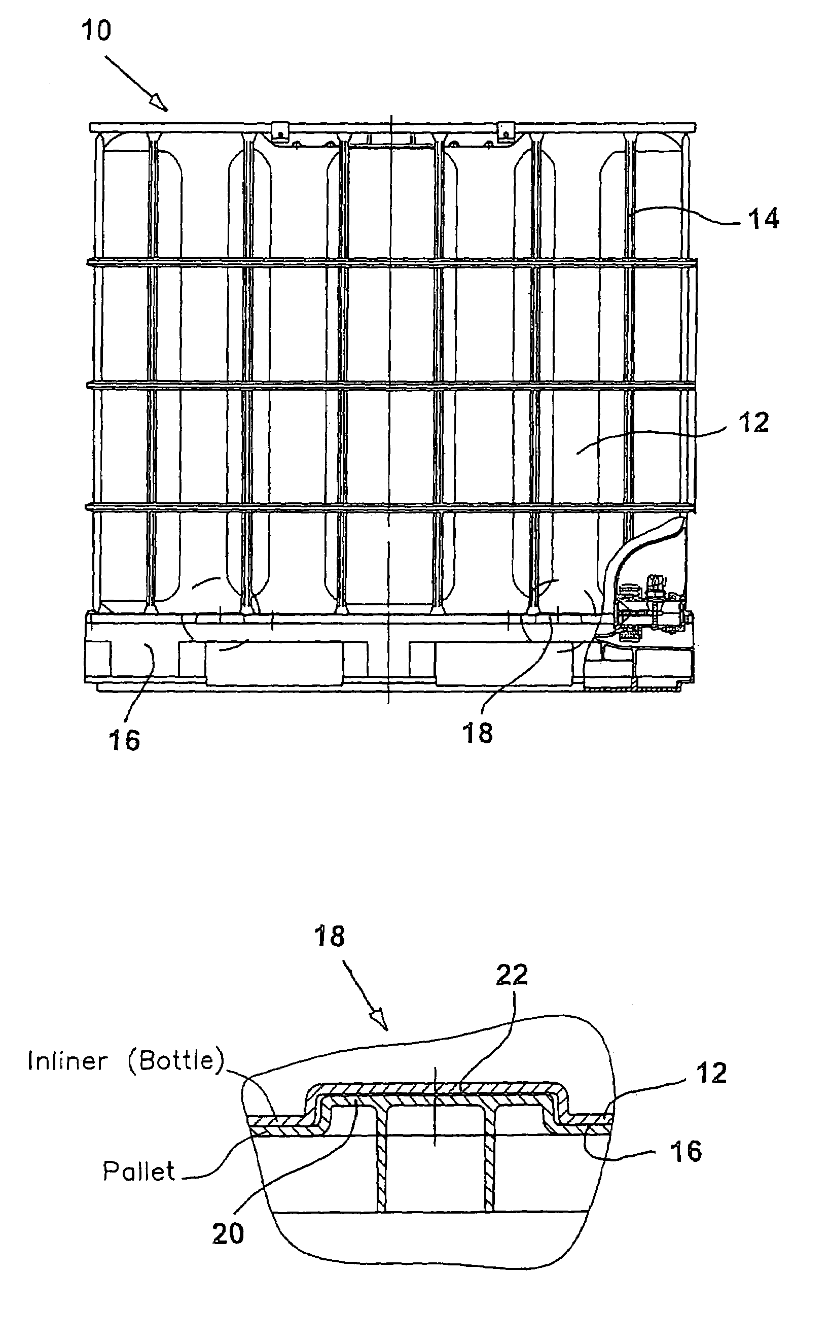
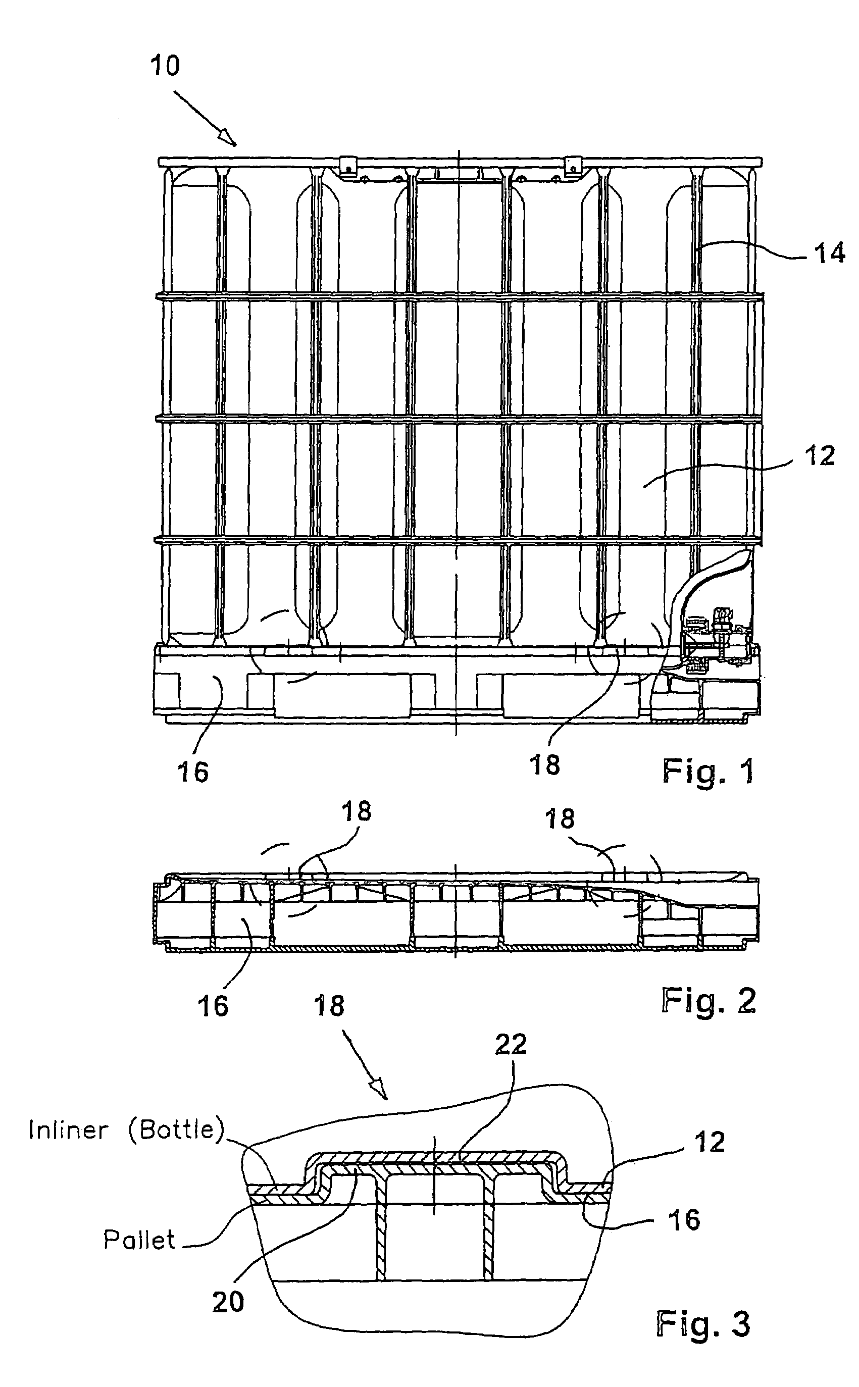
[0039]The pallet container 10 shown in FIG. 1 includes a thin-walled rigid inner container 12 of thermoplastic material for storage and transport of liquid and flowable contents, a cage-like bar frame 14, which closely surrounds as support jacket the inner plastic container 12, and a bottom pallet 16 for placement of the inner plastic container 12 and secure fixation to the cage-like bar frame 14. The circles shown in the bottom region of the inner container and top of the bottom pallet 16 should illustrate the application site of the form-fitting element 18 of the present invention. An additional intermediate plate can be arranged between inner container 12 and bottom pallet 16, which is made e.g. of steel sheet or plastic for covering an open bar frame pallet, or which is made of foamed polystyrene to serve as dampening element. If an additional intermediate plate is so arranged, then the form-fitting means according to the invention, such as e.g. several form-fitting elements, ar...


PUM


Abstract

The invention is directed to a pallet container assembly with a thin-walled rigid inner container of thermoplastic material for the storage and transport of liquid or flowable contents, including a cage-like bar frame closely surrounding as support jacket the inner plastic container, and a bottom pallet for placement of the inner plastic container and secure attachment of the support jacket, wherein there are provided, within the support area of the inner plastic container on the surface of the bottom pallet optionally on the surface of an intermediate plate, respective means (form-fitting means/frictional connection means) which—as viewed in the direction of the horizontal plane—result in a substantial increase of the slip resistance between the downwardly pointing outer surface of the bottom pallet or the intermediate plate.

Description

CROSS-REFERENCES TO RELATED APPLICATIONS[0001]This application is a continuation of prior filed U.S. patent application Ser. No. 10 / 201,462 filed Jul. 23, 2002, U.S. Pat. No. 6,719,162, which is a continuation of prior filed co-pending PCT International Application No. PCT / EP01 / 13650, filed Nov. 23, 2001.[0002]This application claims the priority of German Patent Application Serial No. 200 19 974.9 filed Nov. 23, 2000, the subject matter of which is incorporated herein by reference.[0003]This application claims benefit of prior filed provisional application Appl. No. 60 / 253,264 filed Nov. 27, 2000.BACKGROUND OF THE INVENTION[0004]The invention relates, in general, to a pallet container and more particularly to a pallet container of a type having a thin-walled rigid inner receptacle, preferably made from thermoplastic material for the storage and transport of liquid or free-flowing goods, wherein the plastic container is closely surrounded by an outer cage jacket as a supporting casi...

Claims


Application Information

Patent Timeline
Patent Type & Authority Patents(United States)
IPC IPC(8): B65D19/00B65D19/06B65D19/38B65D19/44B65D77/04B65D77/06
CPCB65D19/06B65D77/0466B65D19/44B65D2519/00815B65D2313/02B65D2313/08B65D2313/10B65D2519/00034B65D2519/00069B65D2519/00164B65D2519/00273B65D2519/00288B65D2519/00318B65D2519/00502B65D2519/00512B65D2519/00572B65D2519/00621B65D2519/00666B65D77/06
Inventor PRZYTULLA, DIETMAR
Owner MAUSER WERKE GMBH
Why Eureka
Try Eureka