Synthetic resin bottle with a handle

a synthetic resin and handle technology, applied in the direction of sealing, container preventing decay, other domestic objects, etc., can solve the problems of bottle and handle sliding, insufficient bottle and handle strength, and the fitting strength cannot reach the initial expected level, so as to reduce friction resistance and increase fitting strength. satisfactory

Inactive Publication Date: 2006-09-19
YOSHINO KOGYOSHO CO LTD
View PDF22 Cites 16 Cited by
  • Summary
  • Abstract
  • Description
  • Claims
  • Application Information

AI Technical Summary

Benefits of technology

[0016]In the first place, it is necessary to determine the shapes of insert portions of the handle adequately in order for the fitting strength to be increased by eliminating such loose fitting of the inserted handle to the bottle that allows the handle to move clatteringly back and forth, from side to side, and up and down.
[0053]The configuration of the embedded projecting portions allows the bottles of larger sizes to be molded without abrasions and with no need of changing the shape of conventional embedded projecting portions.

Problems solved by technology

However, if the PET bottle and the PET handle are used together, the slide between bottle and handle gets worse during the blow molding operation.
Consequently, it becomes insufficient for the bottle to get around the PET handle inserts during the blow molding.
There may be a case where fitting strength fails to reach the initially expected level, or there arises a problem of abrasions on the bottle wall.

Method used


Image

  • Synthetic resin bottle with a handle
  • Synthetic resin bottle with a handle
  • Synthetic resin bottle with a handle

Examples


first embodiment

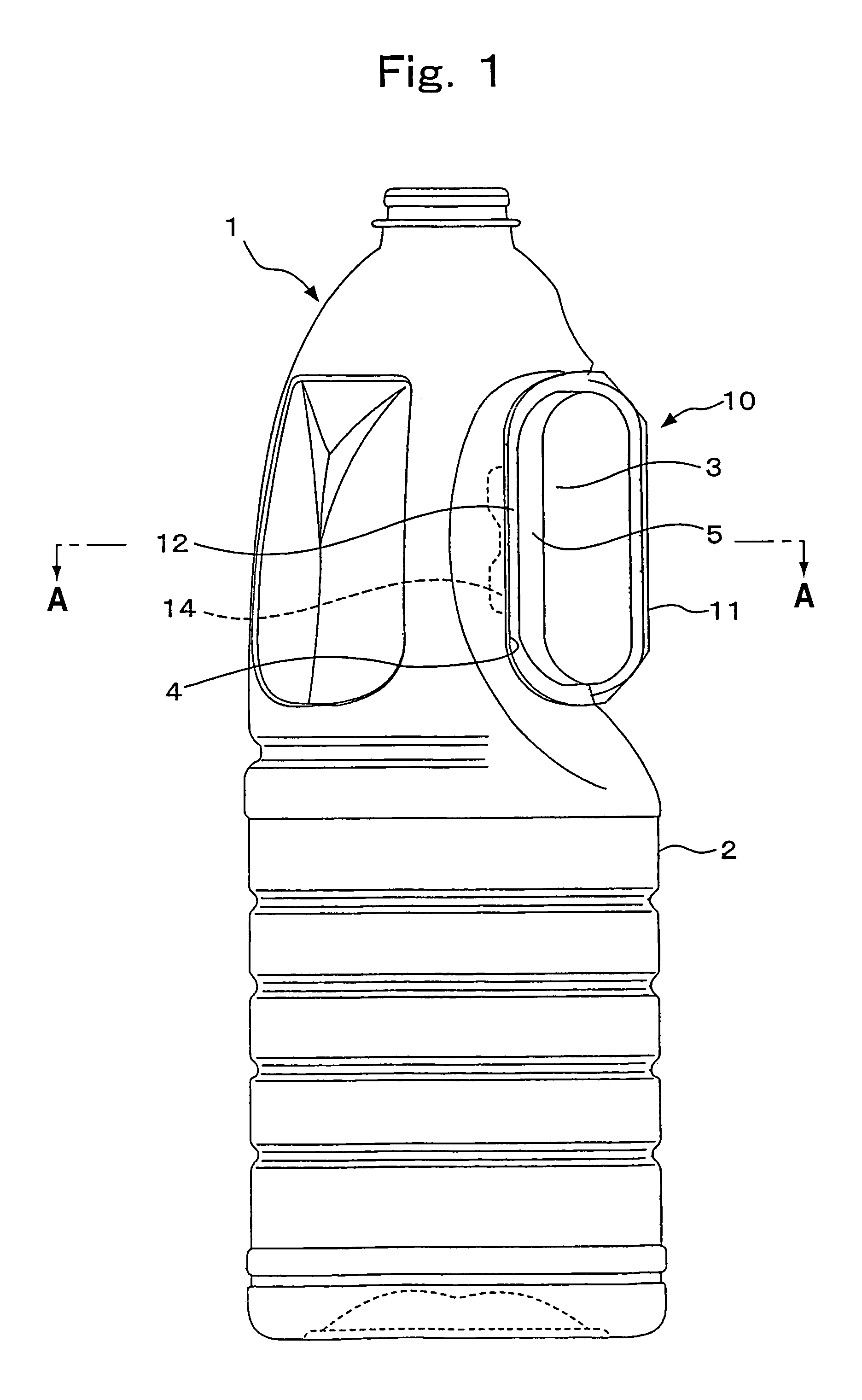
[0083]This invention is further described in respect to preferred embodiments, now referring to the drawings. FIGS. 1–9 show the bottle with a hand in this invention. The bottle of this invention comprises the bottle 1 and the handle 10. The bottle 1 is a biaxially drawn, blow-molded PET product of a large size (1.0 liter or more), and is provided with a recession 3 that has been caved in at the rear of the upper half of the bottomed cylindrical body 2. The handle 10 is an injection-molded PET product, which is fitted firmly to the recession 3 by an insert molding means.

[0084]The recession 3 of the bottle 1 comprises a vertical projecting wall 5, which is located in the center of recession bottom 4, where the flat projecting wall 5 stands upright, except for the upper and lower ends of the recession 3. The projecting wall 5 is relatively wide and extends vertically over the total height of the recession 3, with the wall height being roughly constant from side to side.

[0085]Expanded ...

second embodiment

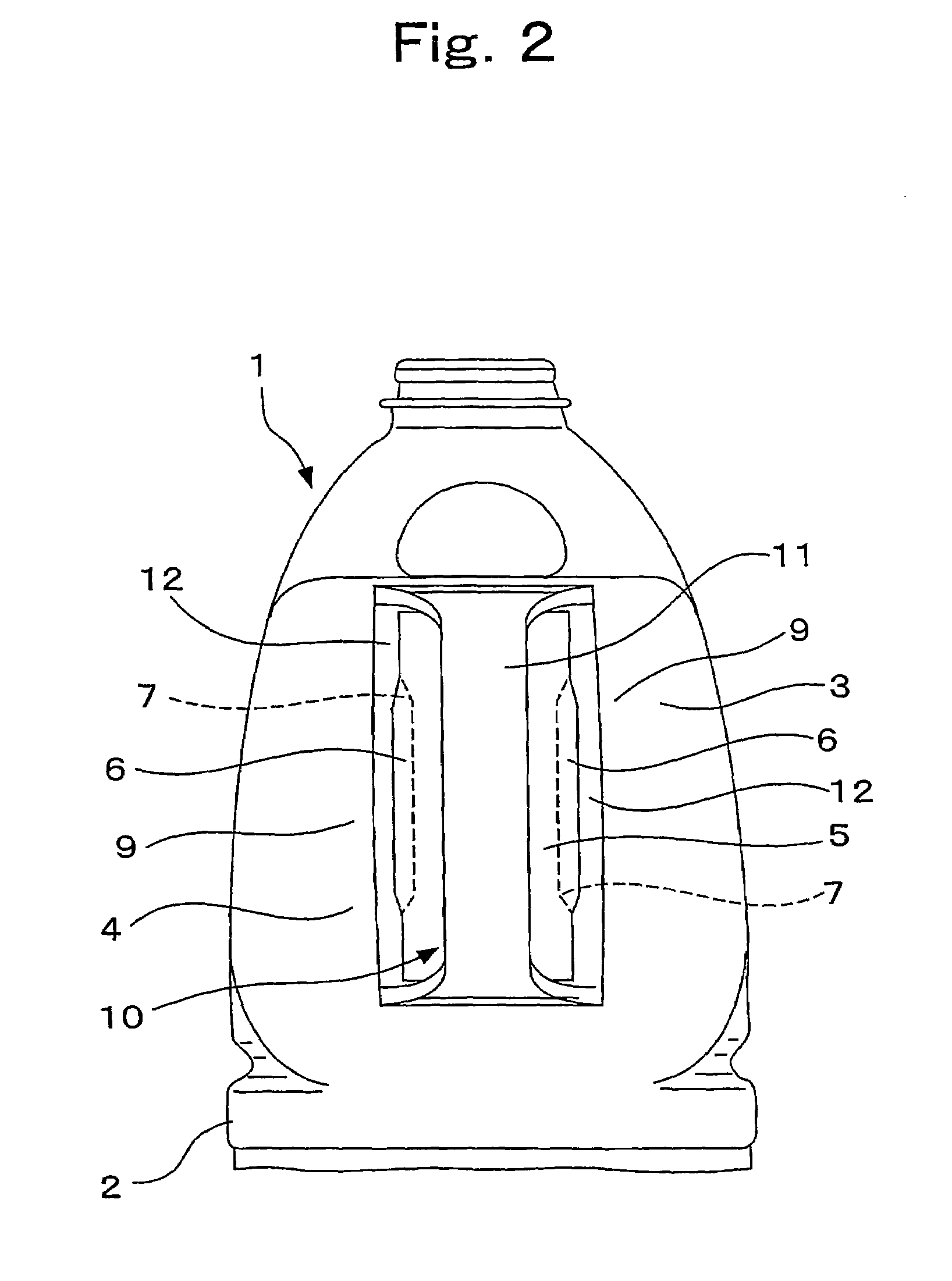
[0092]FIGS. 10–15 show the bottle with a handle in this invention. The bottle in this embodiment comprises the bottle 1 and the handle 10. The bottle 1 is a biaxially drawn, blow-molded PET product of a large size (1.0 liter or more), and is provided with a recession 3 that has been caved in at the rear of the upper half of the bottomed cylindrical body 2. The handle 10 is an injection-molded PET product, which is fitted firmly to the recession 3 by an insert molding means.

[0093]The recession 3 of the bottle 1 comprises a vertical projecting wall 5, which is located in the center of recession bottom 4, where the flat projecting wall 5 stands upright, except for the upper and lower ends of the recession 3. The vertical projecting wall 5 is relatively wide and extends vertically over the total height of the recession 3, with the wall height being roughly constant from side to side.

[0094]Expanded side portions 6 in the vertical ridge shape are disposed on both sides of the vertical pro...

third embodiment

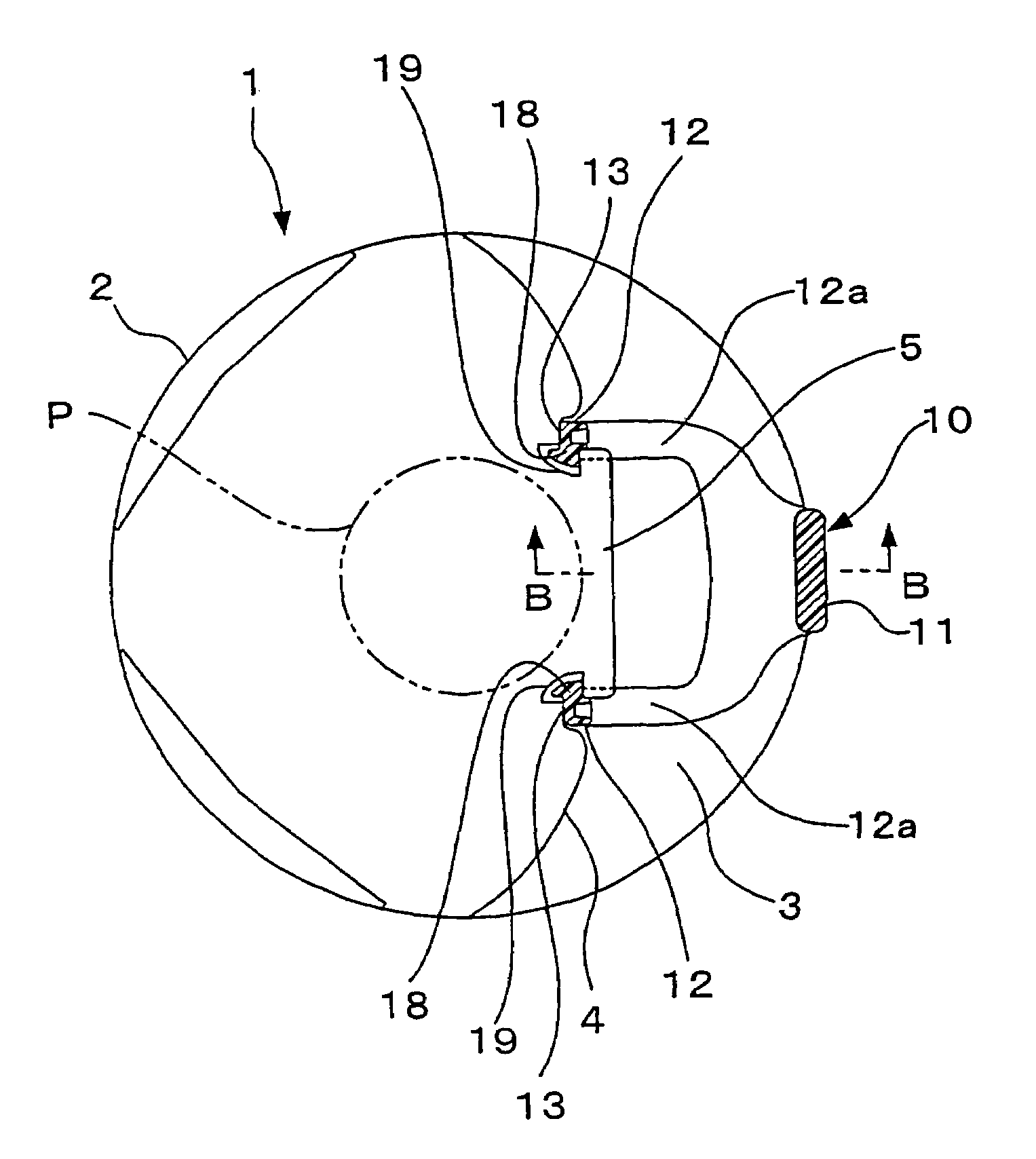
[0107]In this invention, the pair of upper connecting arms 12a has been smoothed over the range indicated by 12C in FIG. 22. Depending on the abrasion development situation, the area to be smoothed can be selected. For example, the pair of lower connecting arms 12a can be smoothed, if necessary.

[0108]The handle 10 is fitted to the bottle 1 by using the handle 10 as the insert and biaxially drawing and blow-molding the bottle 1. At the time of blow molding, the embedded ridge 18 is disposed at a position opposite the neighborhood of outer wall of the preform P in such a manner that the front end face 19 of the embedded ridge 18 is stuck out. The more close to the connecting portion of the grip plate 11 is the outer end face 12b of the connecting arms 12a positioned, the more distant from the outer wall of the preform P it stays, as compared with the front end face 19 of the embedded ridge 18 and the outer end face 13 of the fitting beam 12 (See FIG. 17).

[0109]The PET preform P is exp...


PUM

PropertyMeasurementUnit
degree of crystallinityaaaaaaaaaa
depthaaaaaaaaaa
molding temperatureaaaaaaaaaa

Abstract

A synthetic resin bottle with a handle of this invention comprises a biaxially drawn and blow-molded PET bottle and a handle, an injection-molded product of the same PET resin, which is fitted firmly to the bottle as an insert. The up-and-down property of the surfaces of the handle inserts, which come in contact with the PET bottle, is adjusted in response to the softening and drawing state of the PET preform that is deformed and molded into the bottle. This adjustment causes the friction resistance to be reduced between the handle inserts and the blow-molded PET bottle. The finely textured up-and-down pattern can be easily formed through the tests and adjustments by the surface treatment inside the mold cavity used for the injection molding of the handle. Thus, the optimum surface properties can be obtained in response to the bottle sizes and the handle shapes. Therefore, this invention requires no separate process, such as thermal crystallization. Bottles, which fully get around the handle inserts, have high fitting strength but no abrasion, can be provided at a low cost.

Description

TECHNICAL FIELD[0001]This invention relates to a large-size synthetic resin bottle with a handle, in which the handle is fitted firmly to the bottle by using the handle as an insert and by biaxially drawing and blow-molding the bottle of a polyethylene terephthalate resin (hereinafter referred to as PET resin).BACKGROUND ART[0002]As a large-size bottle, which is easy to handle, there is known a synthetic resin bottle with a handle, in which the handle has been previously injection-molded into a certain shape and is used as an insert, and in which the PET bottle is biaxially drawn and blow-molded. However, it is desired that the handle is made of the same PET as used in the bottle, rather than a polyethylene resin or a polypropylene resin, so that the bottles can be separated and disposed easily at the time of waste disposal.[0003]As conventional art that can meet this demand, Japanese Patent Application (OPI) No. 1994-298253 discloses that the fitting portions of the handle coming i...

Claims


Application Information

Patent Timeline
Patent Type & Authority Patents(United States)
IPC IPC(8): B65D23/10B29C49/06B29C49/08B29C49/20
CPCB65D23/106B29C49/06B29C49/08B29C49/20B29C2049/2017B29C2049/2039B29B2911/14506B29K2067/00B29K2995/0073B29L2031/463B29L2031/7158B29C2049/2069B29C2949/079B29C2949/0715B29C2049/7862B65D23/10B65D25/28
Inventor ITOKAWA, JUNICHIMATSUO, YOSHINORIIIZUKA, TAKAO
Owner YOSHINO KOGYOSHO CO LTD
Why Eureka
Try Eureka