Structure of a swirl generator for liquid

a swirl generator and swirl technology, applied in the direction of baths, douches, physical therapy, etc., can solve the problems of inconvenient repair and the inability to meet the cost benefit of the modern industry, and achieve the effects of convenient assembly and decomposition, improved quality ratio, and reduced assembly tim

Inactive Publication Date: 2006-09-19
CHANG HONG JUN
View PDF5 Cites 23 Cited by
  • Summary
  • Abstract
  • Description
  • Claims
  • Application Information

AI Technical Summary

Benefits of technology

[0010]The assembly of the swirl generator 2 uses the fixation section 215 formed inside the bearing seat 21 to provide assembly with the connecting section 221, 246 of the diversion plate 22 and diversion case 24. Therefore, the components inside the bearing seat 21, namely, diversion plate 22, rotor 23, and diversion case 24, are affixed beforehand to avoid loosening or coming off, so that the outer end of the bearing seat 21 can wedge the water guide cover 25 more easily. During the assembly process, even if the bearing seat 21 is not placed in the exact angle, the components will not be displaced or detached. The present invention allows the assembly of the swirl generator 2 and motor 1 to become easier and quicker. The present invention provides advantages of improvement in the quality ratio, convenient assembly and decomposition, reduction in the assembly time, and cost effectiveness.
[0011]The outside of the bearing seat 21 forms the outer thread of screw 216, allowing the fixed cover 30 to screw on for fixation and quick assembly or decomposition. The present invention improves the problem found in the conventional structure that separate affixation by using screws is required for each part.
[0012]The structure of the swirl extension 3, along with the fixation section 215 inside the bearing seat 21, can make the swirl extension 3 easier to assemble and decompose. The present invention provides a structure that is easier to clean and prevent the filth from accumulating inside the bearing seat 21, thus, allows the swirl extension 3 to operate more smoothly and prolongs the product life.

Problems solved by technology

Since the conventional swirl generator comprises numerous parts, and the assembly is not easy, it has problems of difficulty in assembly and decomposition, thus, causes inconvenience in repair.
Therefore, the convention swirl generator does not meet the cost benefit of the modern industry.

Method used


Image

  • Structure of a swirl generator for liquid
  • Structure of a swirl generator for liquid
  • Structure of a swirl generator for liquid

Examples


Embodiment Construction

[0020]The features and the advantages of the present invention will be more readily understood upon a thoughtful deliberation of the following detailed description of a preferred embodiment of the present invention with reference to the accompanying drawings.

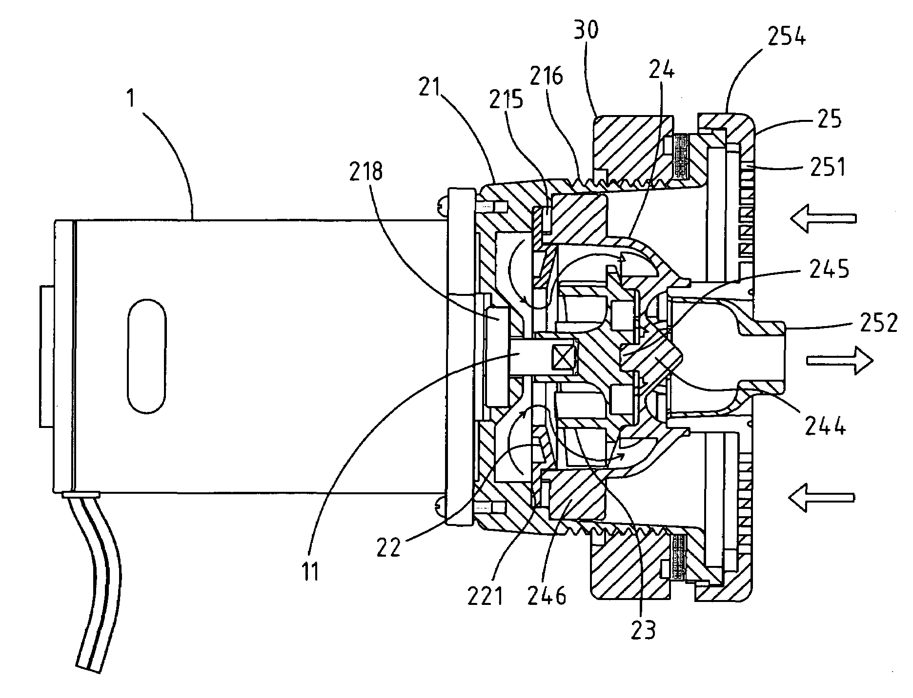
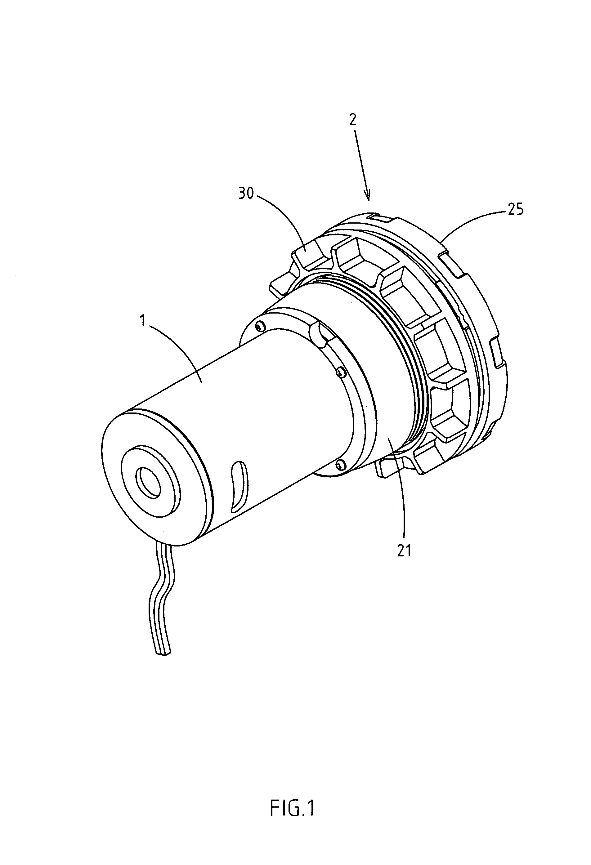
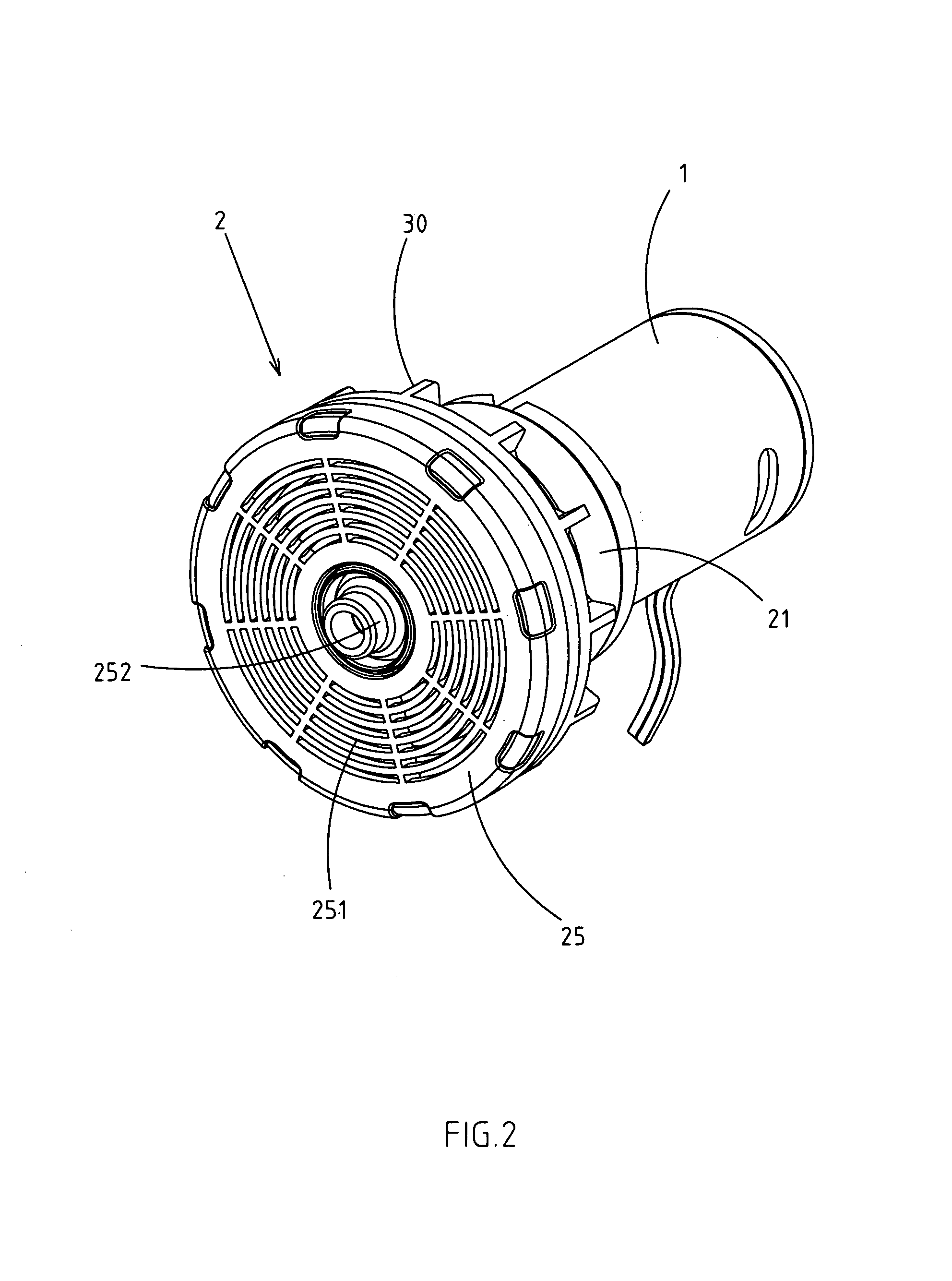
[0021]As shown in FIGS. 1–4, an improved structure of swirl generator for liquid comprises: a motor 1, which head is affixed to a swirl generator 2; the said swirl generator 2 comprises a bearing seat 21 which has a swirl extension 3 inside; the said swirl extension 3 comprises a diversion plate 22, a rotor 23, a diversion case 24 inside the bearing seat 21 in sequence, and which outer opening 211 of the bearing seat 21 is covered by a water guide cover 25; the said bearing seat 21 has a through hole 212 in the center, providing a space for the rotating shaft 11 of the motor 1 to go through to inside the bearing seat 21, and a rotating shaft 11 is inserted into the rotor 23; the inside and circumference of the said rotor 23 form...


PUM


Abstract

The structure of swirl generator for liquid includes a motor with a head affixed to a swirl generator. The bearing seat of the swirl generator forms a fixation section, allowing the swirl extension to be affixed to the inside of the bearing seat easier and quicker, and installing the water guide cover at the opening of the bearing seat. Therefore, the swirl generator structure has advantages of easy assembly and decomposition for repair.

Description

RELATED U.S. APPLICATIONS[0001]Not applicable.STATEMENT REGARDING FEDERALLY SPONSORED RESEARCH OR DEVELOPMENT[0002]Not applicable.REFERENCE TO MICROFICHE APPENDIX[0003]Not applicable.FIELD OF THE INVENTION[0004]The present invention relates generally to a swirl generator for liquid.BACKGROUND OF THE INVENTION[0005]The swirl generator for liquid refers to a structure that is mainly used on environments or objects such as massage tub, foot spa, hot spring pool or others that require spurting turbulent flow of water to generate swirl. It mainly comprises a drive motor and swirl nozzle, in which the drive motor drives the rotor inside the swirl nozzle to draw in water, adds pressure, then spurts the water column in strong force from the nozzle or keeps the water from staying still so as to improve the quality and increase the oxygen content of the water. Since the conventional swirl generator comprises numerous parts, and the assembly is not easy, it has problems of difficulty in assemb...

Claims


Application Information

Patent Timeline
Patent Type & Authority Patents(United States)
IPC IPC(8): B05B1/34
CPCA61H33/6063A61H33/6047A61H33/0087
Inventor CHANG, HONG-JUN
Owner CHANG HONG JUN
Why Eureka
Try Eureka