High-stability valve arrangement for a governor valve

a governor valve and high-stability technology, which is applied in the direction of functional valve types, machines/engines, mechanical apparatus, etc., can solve the problems of large opening between the cutoff plug and the seat wall, excessive vibration, and possible valve failure, and achieve high-stability valve arrangemen

Inactive Publication Date: 2006-09-19
ELLIOTT CO
View PDF21 Cites 35 Cited by
  • Summary
  • Abstract
  • Description
  • Claims
  • Application Information

AI Technical Summary

Benefits of technology

[0015]The above objects are accomplished with a high stability valve arrangement for a governor valve made in accordance with the present invention. The valve arrangement includes a cutoff plug having a lateral concave surface of radius of curvature rq. The lateral concave surface tapers to form an end portion having a substantially circular cross section of radius re. A seat is located opposite the cutoff plug and has a central aperture along a central axis of the valve arrangement. The central aperture is defined at least in part by a convex surface of the seat having radius of curvature R.

Problems solved by technology

It is known in the art that steam turbine governor valves often encounter flow instabilities at some operating positions (i.e., lifts) which can cause noise, excessive vibration, and, possibly, valve failure.
Flow induced instability is believed to be the most likely cause of catastrophic failures in steam turbine governor valves known in the prior art.
Steady state forces are inadequate to explain the damage observed in practice in the prior art.
In the undesirable core flow pattern, the resulting sheet of jet flow impinging on itself is unstable, producing a shifting pattern beneath the plug.
However, at high lifts (i.e., high flow rate) the opening between the cutoff plug and the seat wall is large compared to the seat radius of curvature.
A sheet of unstable flow from the seat wall to the center of the toroid opening beneath the cutoff plug results.
This flow pattern is unstable and produces turbulence in

Method used


Image

  • High-stability valve arrangement for a governor valve
  • High-stability valve arrangement for a governor valve
  • High-stability valve arrangement for a governor valve

Examples


Embodiment Construction

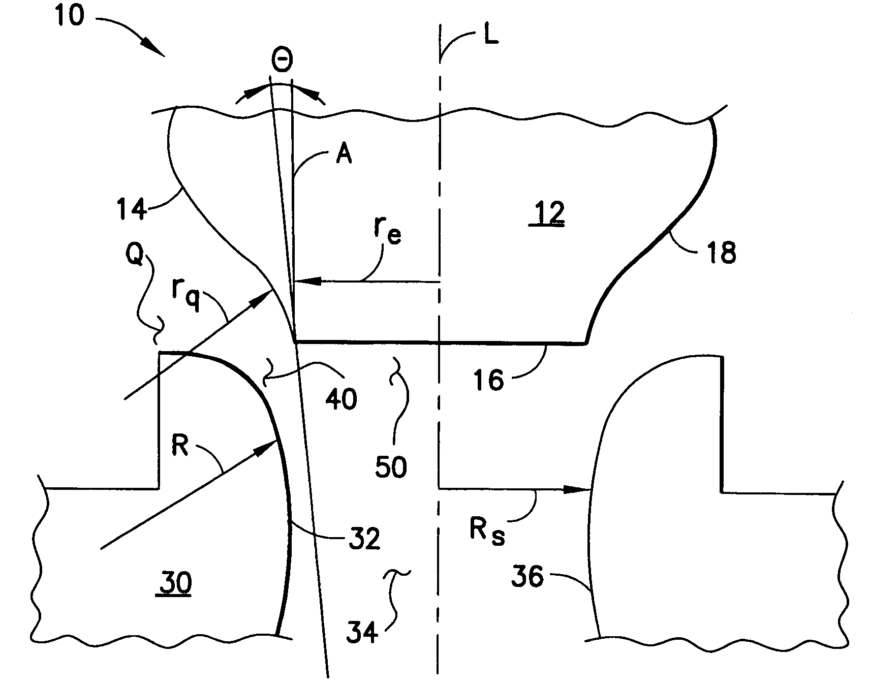
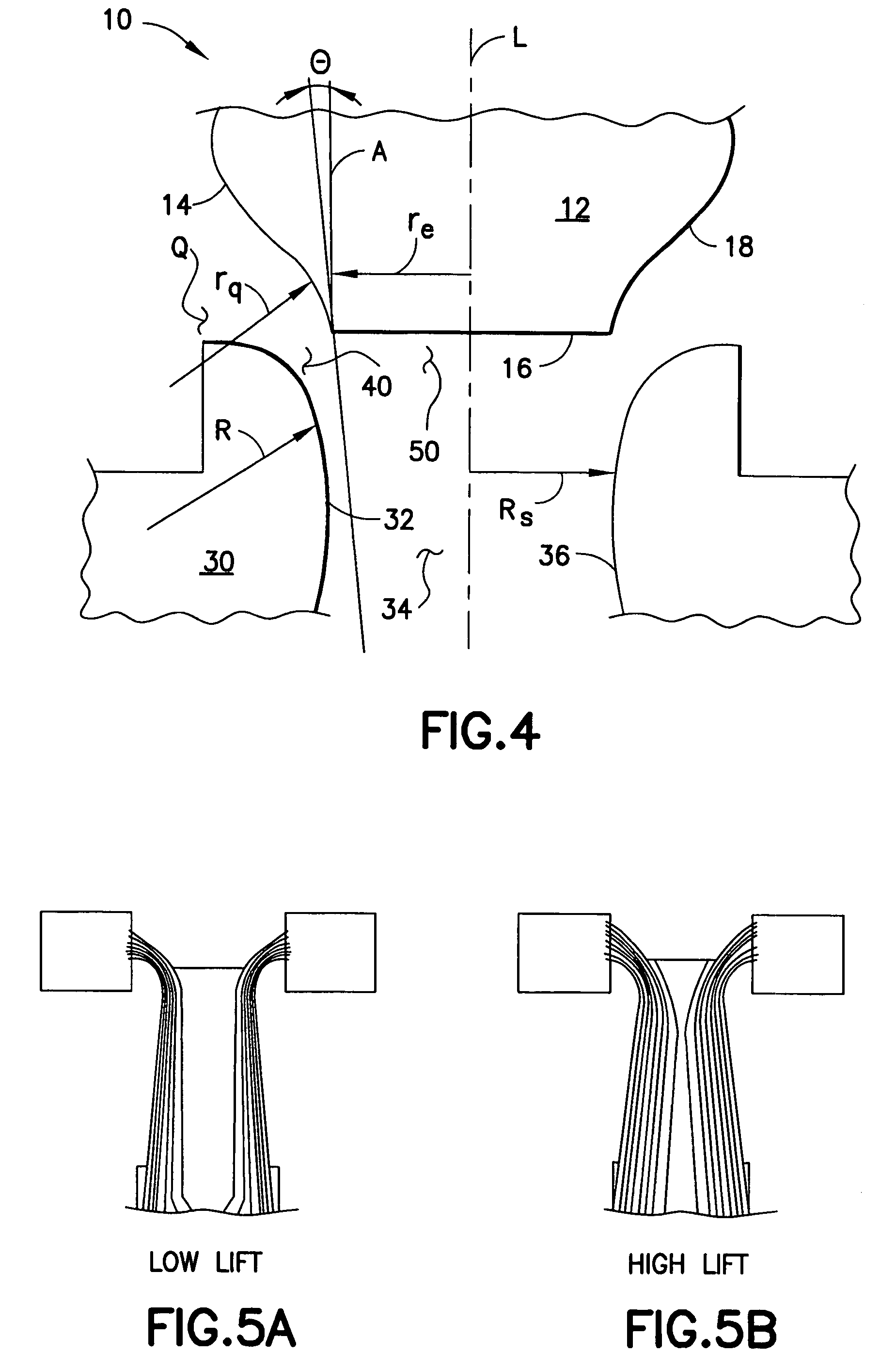
[0024]Referring to FIG. 4, the present invention is a valve arrangement 10 that includes a cutoff plug 12 having a lateral concave surface 14 that tapers to form an end portion 16 that is substantially circular in horizontal cross section. The intersection of the end portion 16 and the lateral concave surface 14 of the cutoff plug 12 defines an abrupt cutoff corner 18. The valve arrangement 10 further includes a valve seat 30 with a convex surface 32. The valve seat 30 has a central aperture 34 defined at least in part by the convex surface 32. The upper end of the central aperture 34 faces the cutoff plug 12. Both the central aperture 34 and the cutoff plug 12 are aligned on a valve arrangement central axis L. Fluid passes through the central aperture 34 in the course of operation of the valve arrangement 10. The convex surface 32 is a portion of a seat wall 36 that laterally defines the central aperture 34. The cutoff corner 18 of the cutoff plug 12 and the convex surface 32 of th...


PUM


Abstract

A valve arrangement (10) for reducing the instability of fluid flow in a compressible flow governor valve includes a cutoff plug (12) with a lateral concave surface (14) and an end portion (16) having a substantially circular cross section, and a seat (30) with a convex surface (32). The lateral concave surface (14) and the end portion (16) of the cutoff plug (12) define an abrupt cutoff corner (18). The radius (re) of the end portion (16) of the cutoff plug (12) is less than the radius (Rs) of the seat (30). The radius of curvature (R) of the seat (30) is less than the radius of curvature (rq) of the lateral concave surface (14) of the cutoff plug (12). The configuration of the cutoff plug (12) and seat (30) enhances the annular flow pattern beneath the cutoff plug (12) at all lift positions thus reducing flow instability.

Description

BACKGROUND OF THE INVENTION[0001]1. Field of the Invention[0002]The present invention relates to the control of the flow of fluid in valves and, more particularly, to a valve arrangement offering stability over a range of fluid flow rates.[0003]2. Description of the Prior Art[0004]Governor valves are known for use in controlling the operating pressure in fluid systems, such as steam turbine systems. In a steam turbine system, the inlet port of the steam turbine is connected to the outlet port of a governor valve that regulates or controls the fluid flow entering the steam turbine.[0005]It is known in the art that steam turbine governor valves often encounter flow instabilities at some operating positions (i.e., lifts) which can cause noise, excessive vibration, and, possibly, valve failure. Steam turbine governor valves typically employ a cutoff plug that engages a valve seat to regulate the steam flow. The valve seat typically resembles a portion of a toroid. The cutoff plug in ope...

Claims


Application Information

Patent Timeline
IPC IPC(8): F16K1/12F01D25/00F01D17/14F16K1/34F16K1/36F16K1/42F16K25/00F16K47/00
CPCF16K1/34F16K1/36F16K47/00F16K25/00F16K1/42
Inventor HARDIN, JAMES R.
Owner ELLIOTT CO
Why Eureka
Try Eureka