Optical system with reflection-angle-selective mirror

a mirror and optical system technology, applied in the field of optical systems with reflection-angle selective mirrors, can solve the problems of stray light rays reflected from the mirror, lack of perfect collimation of the incident primary beam, and stray light, so as to improve the signal-to-noise ratio and reduce the chance of damage to optical components

Inactive Publication Date: 2006-09-19
RAYTHEON CO
View PDF12 Cites 65 Cited by
  • Summary
  • Abstract
  • Description
  • Claims
  • Application Information

AI Technical Summary

Benefits of technology

[0007]The present invention controls the stray light in an optical system by altering the properties of a mirror to reflect at only a single selected angle of incidence or a selected range of angles of incidence. Stray light at other angles is not reflected, and is either absorbed in the reflection-angle-selective mirror or passed through the reflection-angle-selective mirror. The stray light does not reach the detector or other structure to which the primary beam is reflected. The present approach is compact, because it requires only the application of a thin coating structure to the mirror substrate and does not require the use of mechanical masks. The present approach allows the entire reflection-angle-selective mirror surface to be utilized in reflecting the primary beam, and also allows the use of larger mirrors than previously possible.
[0011]Thus, the reflection-angle-selective mirror is reflective for the primary light beam incident at or near the design incidence angle, and does not reflect light incident at other angles greater than the acceptance-angle deviation. Stray light from any source incident at other angles is not reflected. The result is improved signal-to-noise ratio in the primary beam, and a reduced chance of damage of optical components due to stray or “off axis” light. The optical system is compact because the thin coating structure is applied to the surface of the substrate and no aperture or other type of separate mechanical mask is required.

Problems solved by technology

However, in many cases there are stray light rays reflected from the mirror at other angles.
The stray light rays may result from a lack of perfect collimation of the incident primary beam, reflections from surfaces within the optical system such as lens coatings or supports, or from other light sources.
Where the primary beam is in the infrared, the stray light may result from the radiation of the internal structure of the optical system.
The stray light rays may have several adverse effects.
The signal resolution of the optical system may be compromised.
There also may be damage to sensitive optical components that are not designed for compatibility with the stray light.
The mechanical masks are effective, but they lead to an increase in the size of the optical system because they are spaced apart from the mirror.
Additionally, the mechanical masks limit the size of the useful area of the mirror.

Method used


Image

  • Optical system with reflection-angle-selective mirror
  • Optical system with reflection-angle-selective mirror
  • Optical system with reflection-angle-selective mirror

Examples


Embodiment Construction

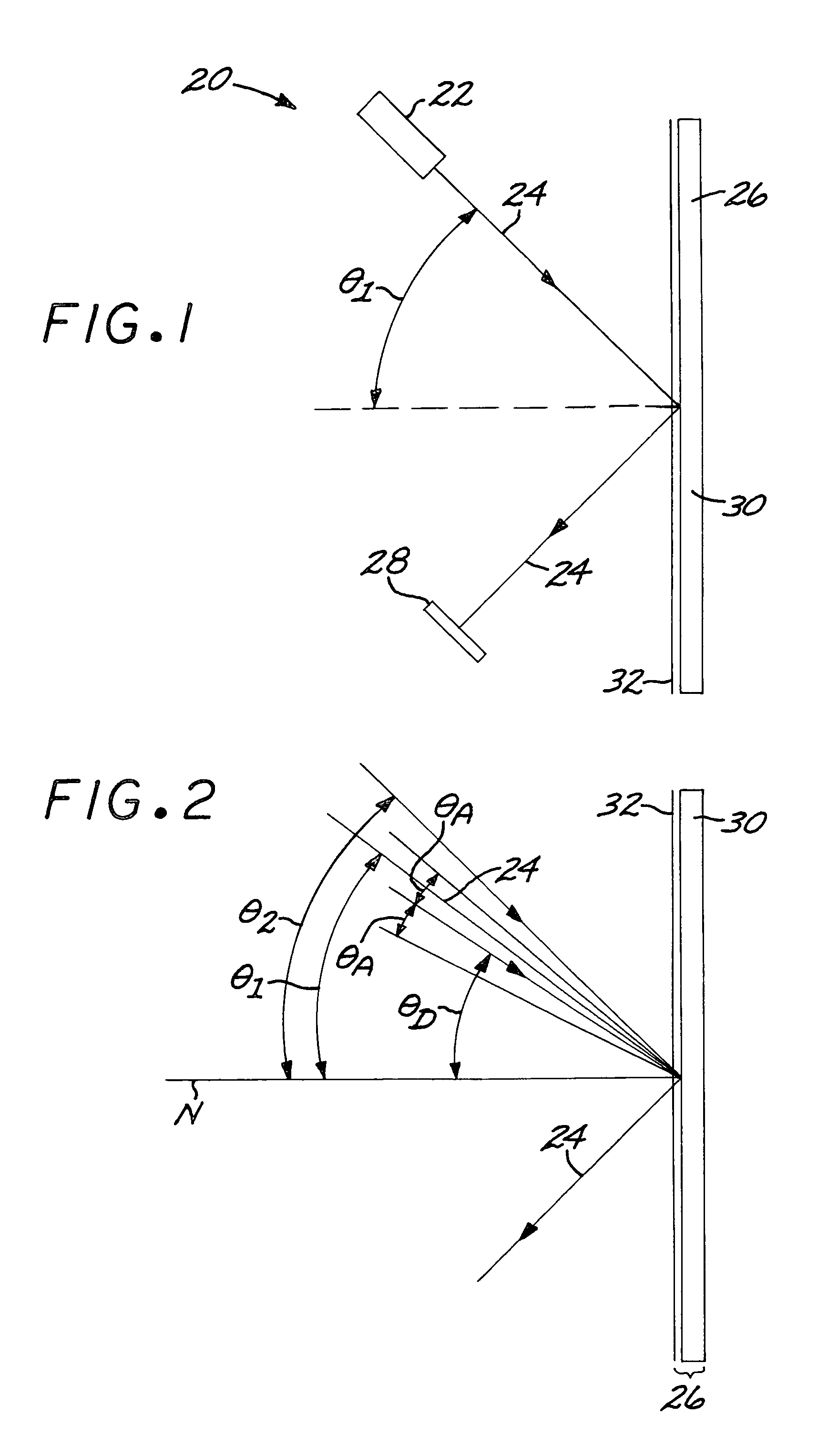
[0020]FIG. 1 depicts an optical system 20 comprising a light source 22 having as an output a primary beam 24 of light. The light source 22 may be of any type, with a visible or infrared laser being an example. The output beam of the light source, which is the primary beam 24, is incident upon and reflects from a reflection-angle-selective mirror 26 to a detector 28. In practice, optical systems 20 usually have more and / or different optical elements in addition to the reflection-angle-selective mirror 26, but these illustrated optical elements are sufficient to present the basic features of the invention.

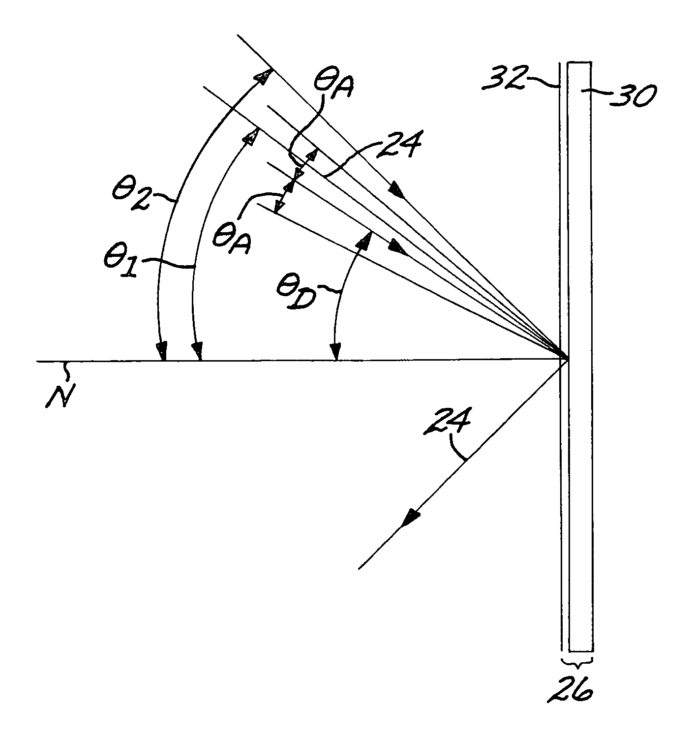
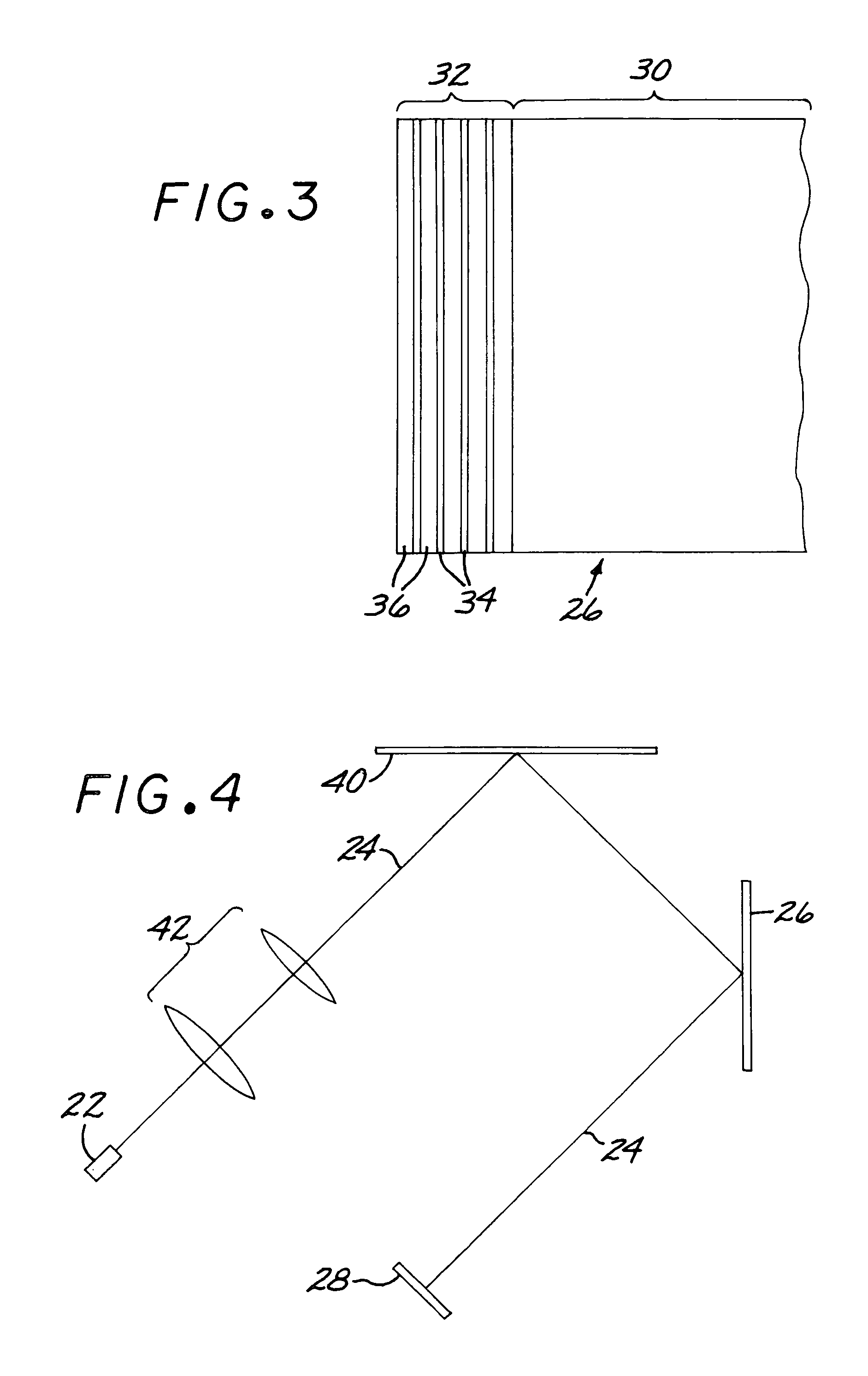
[0021]The reflection-angle-selective mirror 26 includes a substrate 30 and a reflection-angle-selective coating structure 32 deposited upon the substrate 30. FIG. 2 illustrates the angular performance of the reflection-angle-selective mirror 26. The reflection-angle-selective coating structure 32 has a higher reflectance for light that is incident upon the reflection-angle-selective ...


PUM


Abstract

An optical system includes a reflection-angle-selective mirror having a substrate, and a reflection-angle-selective coating structure deposited on the substrate. The reflection-angle-selective coating structure has a higher reflectance for light that is incident upon the reflection-angle-selective coating structure at a first incidence angle within an acceptance-angle deviation from a design incidence angle than for light that is incident upon the reflection-angle-selective coating structure at a second incidence angle greater than the acceptance-angle deviation from the design incidence angle. The optical system may also include a light source.

Description

[0001]This application is a continuation-in-part of application Ser. No. 10 / 831,078, filed Apr. 22, 2004, now U.S. Pat. No. 6,992,830, for which priority is claimed and whose disclosure is incorporated by reference.[0002]This invention relates to an optical system and, more particularly, to an optical system having a mirror which reflects light at a selected angle or range of angles but not at other angles.BACKGROUND OF THE INVENTION[0003]Many optical systems contain powered or unpowered mirrors. A mirror reflects a primary beam of incident light at an angle equal to the angle of incidence. In the ideal case where there is a single perfectly collimated incident primary beam, the reflected beam contains only light from that incident primary beam. However, in many cases there are stray light rays reflected from the mirror at other angles. The stray light rays may result from a lack of perfect collimation of the incident primary beam, reflections from surfaces within the optical system...

Claims


Application Information

Patent Timeline
Patent Type & Authority Patents(United States)
IPC IPC(8): G02B5/08G02B1/10G02B27/00G02B5/28
CPCG02B27/1033G03B21/14G02B27/142
Inventor MITCHELL, DANIEL BRUCE
Owner RAYTHEON CO
Why Eureka
Try Eureka