Planar light source

a light source and surface technology, applied in the direction of planar/plate-like light guides, lighting and heating apparatus, instruments, etc., can solve the problems of inconvenient application of fluorescent scattering layer (printed) on light guide plates, inability to obtain desired color, and inability to obtain white and intermediate color of surface illuminan

Inactive Publication Date: 2006-09-19
ROHM CO LTD
View PDF24 Cites 62 Cited by
  • Summary
  • Abstract
  • Description
  • Claims
  • Application Information

AI Technical Summary

Benefits of technology

[0028]The illumination of the surface illuminant can be kept substantially uniform over the entire surface thereof by compensating for the attenuation of the light emitted to the light guide

Problems solved by technology

It has been known that a problem occurs in which a surface illuminant having white and intermediate color can not be obtained since LED is not capable of emitting white or intermediate color light when LEDs are used as light source.
However, it is inconvenient that the fluorescent scattering layer should be applied (printed) on the light guide plate since the fluorescent material is directly applied upon the light guide plate in the surface illuminant as set forth in paragraph (1).
Si

Method used


Image

  • Planar light source
  • Planar light source
  • Planar light source

Examples


first embodiment

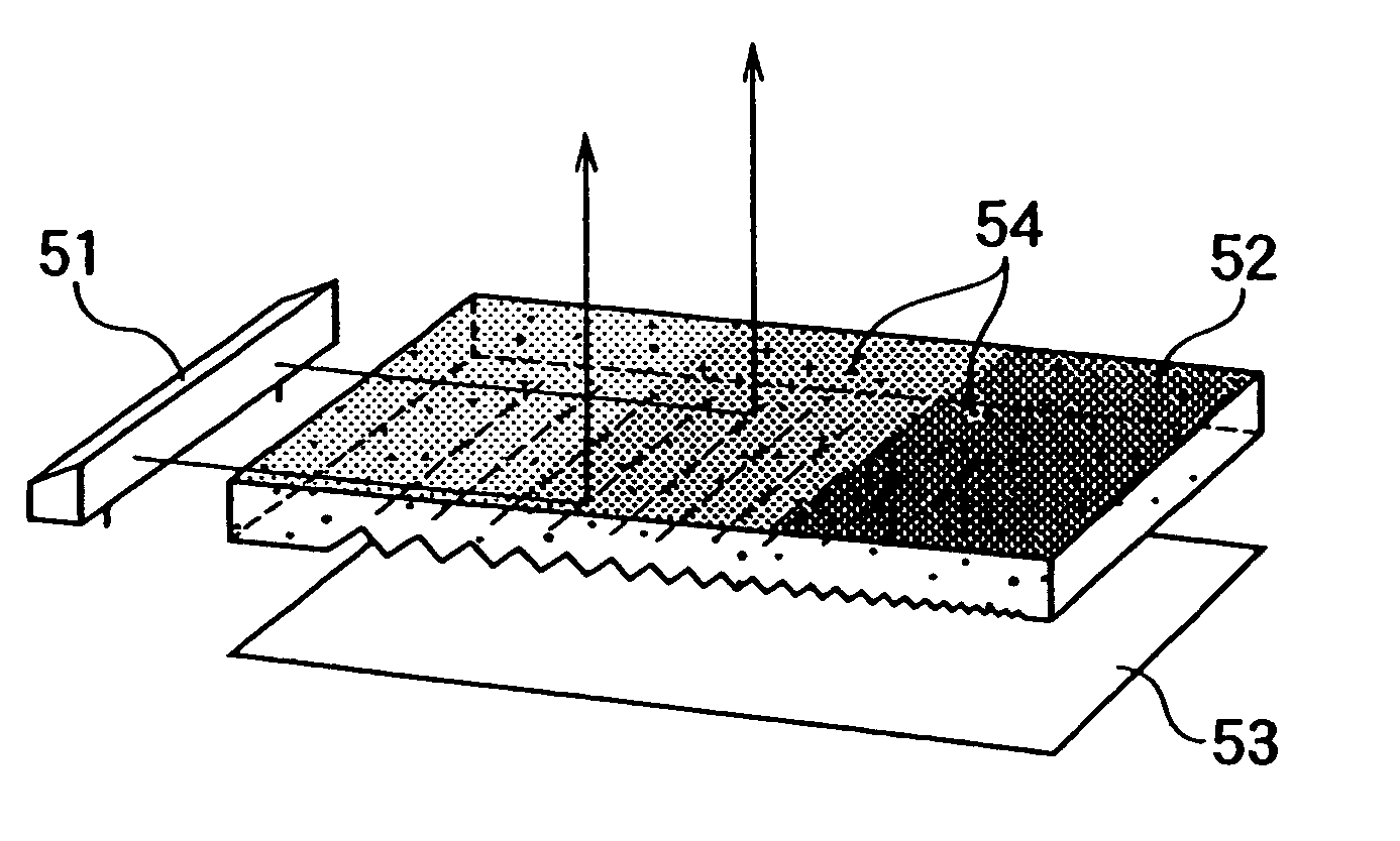
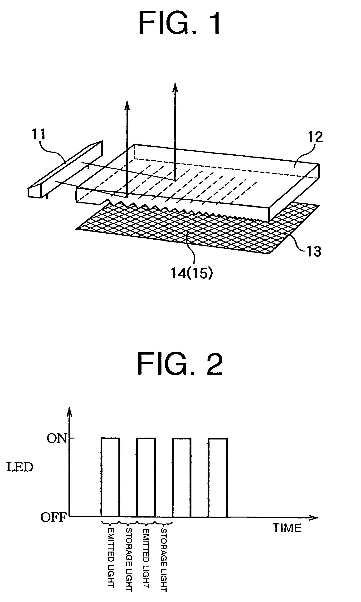
[0037]In FIG. 1, reference numerals 11, 12 and 13 denote a light source; a light guide plate made of a colorless transparent synthetic resin such as polycarbonate or acrylic resin, which is formed on its reverse side with prism-like grooves; and a reflective film made of PET or polycarbonate, respectively. These structures are substantially identical with those of prior art which have been described with reference to FIG. 6.

[0038]In the surface illuminant, the light guide plate 12 is substantially rectangular in shape. The light source 11 is disposed adjacent to the light guide plate 12 so that light is incident upon one end face of the light guide plate 12 from, for example blue color LEDs. The reflective film 13 is disposed to cover the reverse side of the light guide plate 12. A wave length converting layer 14 is provided on the reflective film 13.

[0039]The wave length converting layer 14 is formed by applying a solution of a wave-length converting material such as a fluorescent ...

second embodiment

[0045]The first embodiment in which the reflective film comprises the fluorescent material has been described. Now, a second embodiment of the surface illuminant of the present invention will be described. The surface illuminant comprises a light storage material (a material which absorbs the light rays emitted from the light source for emitting light for a predetermined period of time after light rays from the light source disappear, for example, “N YAKOH” (trade name) manufactured by Nemoto Kagaku Co. Ltd.) in lieu of the reflective film.

[0046]In the second embodiment, the reflective film made of a synthetic resin includes a light storage material 15. The light storage material 15 which is in the form of a solution including a resin as a binder and an appropriate solvent similarly to the case of said fluorescent material is applied on the reflective film or alternatively the light storage material 15 is incorporated in the transparent (transmissive) reflective film. If the light s...

third embodiment

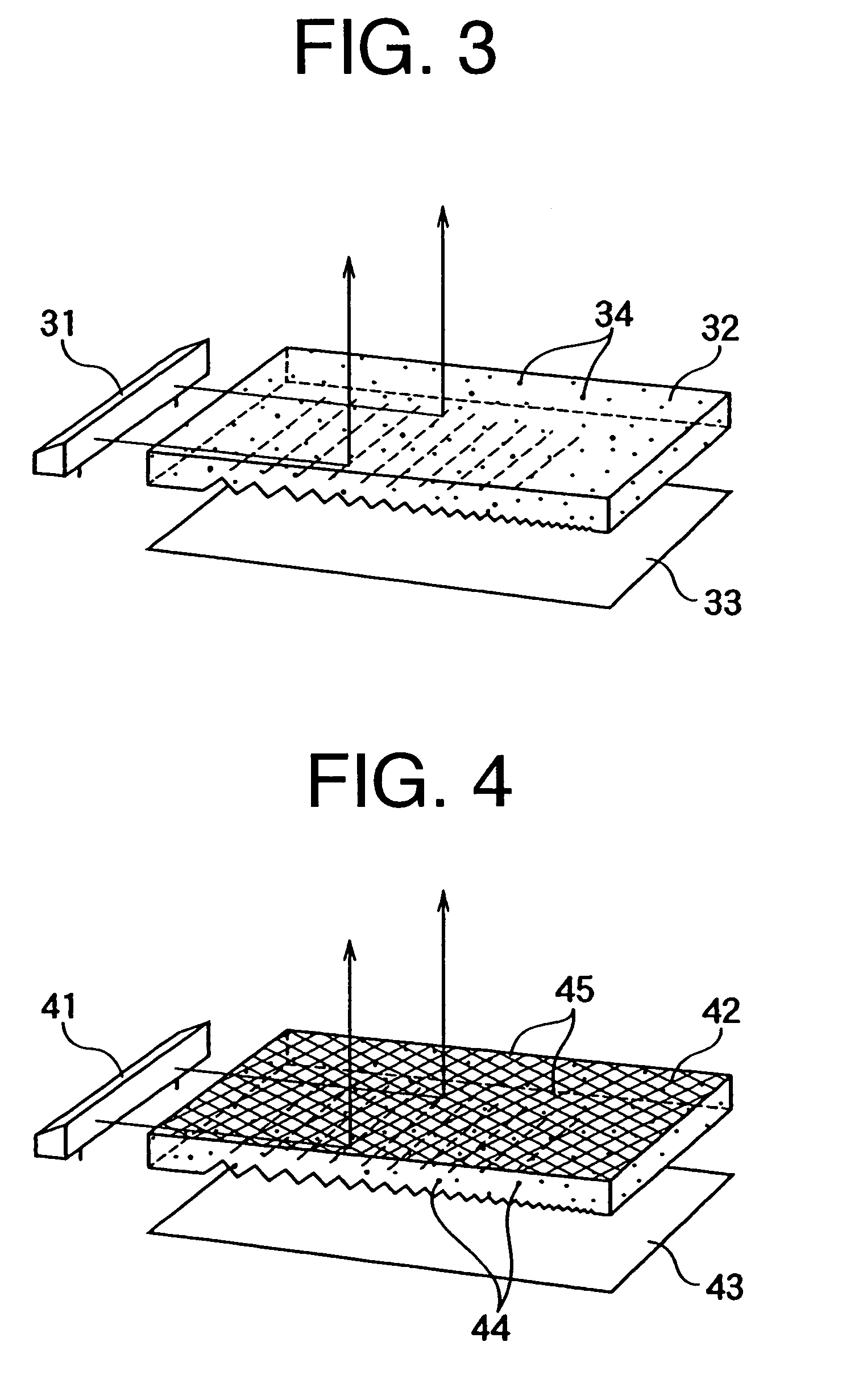
[0048]FIG. 3 shows a third embodiment of the present invention. In FIG. 3, reference numerals 31, 32 and 33 denote a light source; a light guide plate made of a colorless transparent synthetic resin such as polycarbonate or acrylic resin, which is formed on its reverse side prism-like grooves; and a reflective film made of PET or polycarbonate, respectively.

[0049]The light guide plate 32 is substantially rectangular in shape. The light source 31 is disposed adjacent to the light guide plate 32 so that light is incident upon one end face of the guide plate 32 from, for example blue color LEDs. The reflective film 33 is disposed to cover the reverse side of the light guide plate 32.

[0050]The structure is substantially identical with that of the prior art shown in FIG. 6. In the third embodiment of the surface illuminant of the present invention, the light guide plate 32 is made of a colorless transparent synthetic resin such as polycarbonate or acrylic resin, in which a light storage ...


PUM


Abstract

A surface illuminant comprises a light source 11 consisting of LEDs, a light guide plate 12 which is optically coupled to said light source for guiding the light to one side thereof and a reflective film 13 which is disposed on the other opposite side of said light guide plate. The light guide plate 12 is made of a material into which a wave length converting material 14 or a light storage material 15 such as fluorescent material is incorporated. A desired color light can be obtained by converting the wave length of the light from the light source 11 or light can be emitted by storing the light when the light source is turned off.

Description

TECHNICAL FIELD[0001]The present invention relates to a surface illuminant including light emitting diodes (LEDs) and the like which are used as a light source and in particular to a surface illuminant which is capable of emitting a desired color light and is capable of reducing the electric power consumption.BACKGROUND TECHNOLOGY[0002]LED back light sources using a reflection plate have been widely used as a surface illuminant for compact display used for, for example, cellular phones.[0003]FIG. 6 is an exploded perspective view showing a prior art surface illuminant which is exploded. In the drawing, a reference numeral 101 denotes a light source comprising, for example, LEDs or CFL (cold fluorescent tubes); 102 denotes a light guide plate which is adjacent to said light source. The light guide plate 102 is formed of a white and transparent plate made of polycarbonate or acrylic resin, etc. The light guide plate 102 has a flat face from which light is emitted and a reverse face on...

Claims


Application Information

Patent Timeline
IPC IPC(8): F21V7/04G02F1/13F21V8/00
CPCG02B6/005G02B6/0038
Inventor OSAWA, HIDEHARU
Owner ROHM CO LTD
Why Eureka
Try Eureka