Blower housing and cabinet with improved blower inlet airflow distribution

a technology of inlet airflow and blower housing, which is applied in the field of blower housing and cabinet with, can solve the problems of inability to expand the capacity of the blower within a given cabinet size, and achieve the effect of improving the inlet airflow to the blower

Inactive Publication Date: 2006-09-19
TRANE INT INC
View PDF7 Cites 24 Cited by
  • Summary
  • Abstract
  • Description
  • Claims
  • Application Information

AI Technical Summary

Benefits of technology

[0004]The present invention provides an improved airhandling blower and cabinet combination wherein the configuration of the blower housing and its location within and with respect to the cabinet provides for improved inlet airflow to the blower.
[0006]The combination of axial and radial dimensional changes of the housing walls with respect to the blower impeller axis of rotation permits the installation of a blower in a cabinet of a predetermined size and wherein the blower has an increased capacity, and further wherein the combination exhibits an improved distribution of airflow into the air inlets of the blower. Accordingly, a more efficient airhandling apparatus is provided which may also be more quiet than prior art airhandling apparatus.

Problems solved by technology

One problem faced by prior art airhandling blowers is the inability to expand the capacity of the blower within a given cabinet size beyond a certain blower housing size, since the physical dimensions of the blower housing of increased capacity prevent installation in a cabinet without redesigning or increasing the size of the cabinet itself.

Method used


Image

  • Blower housing and cabinet with improved blower inlet airflow distribution
  • Blower housing and cabinet with improved blower inlet airflow distribution
  • Blower housing and cabinet with improved blower inlet airflow distribution

Examples


Embodiment Construction

[0019]In the description which follows, like parts are marked throughout the specification and drawings with the same reference numerals, respectively. The drawing figures may not, in all instances, be to scale in the interest of clarity and conciseness.

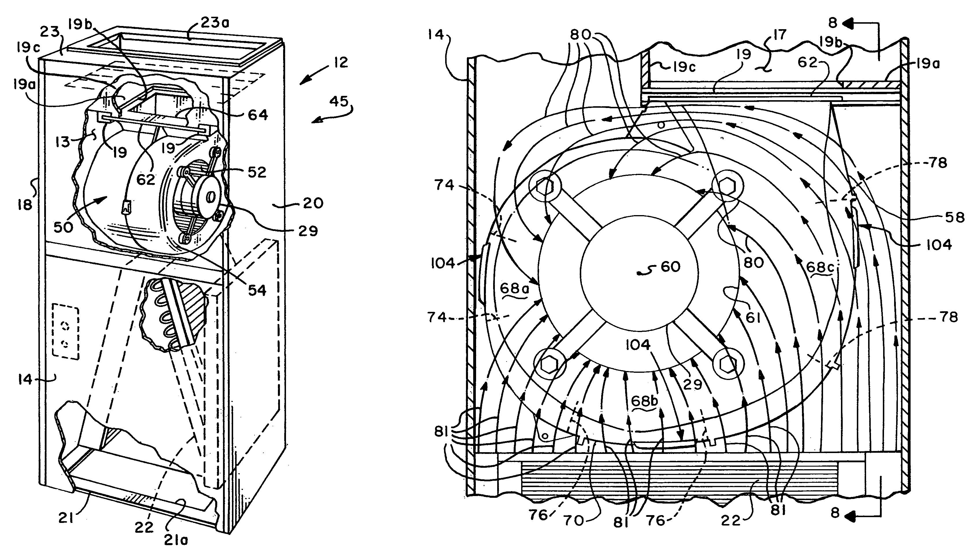
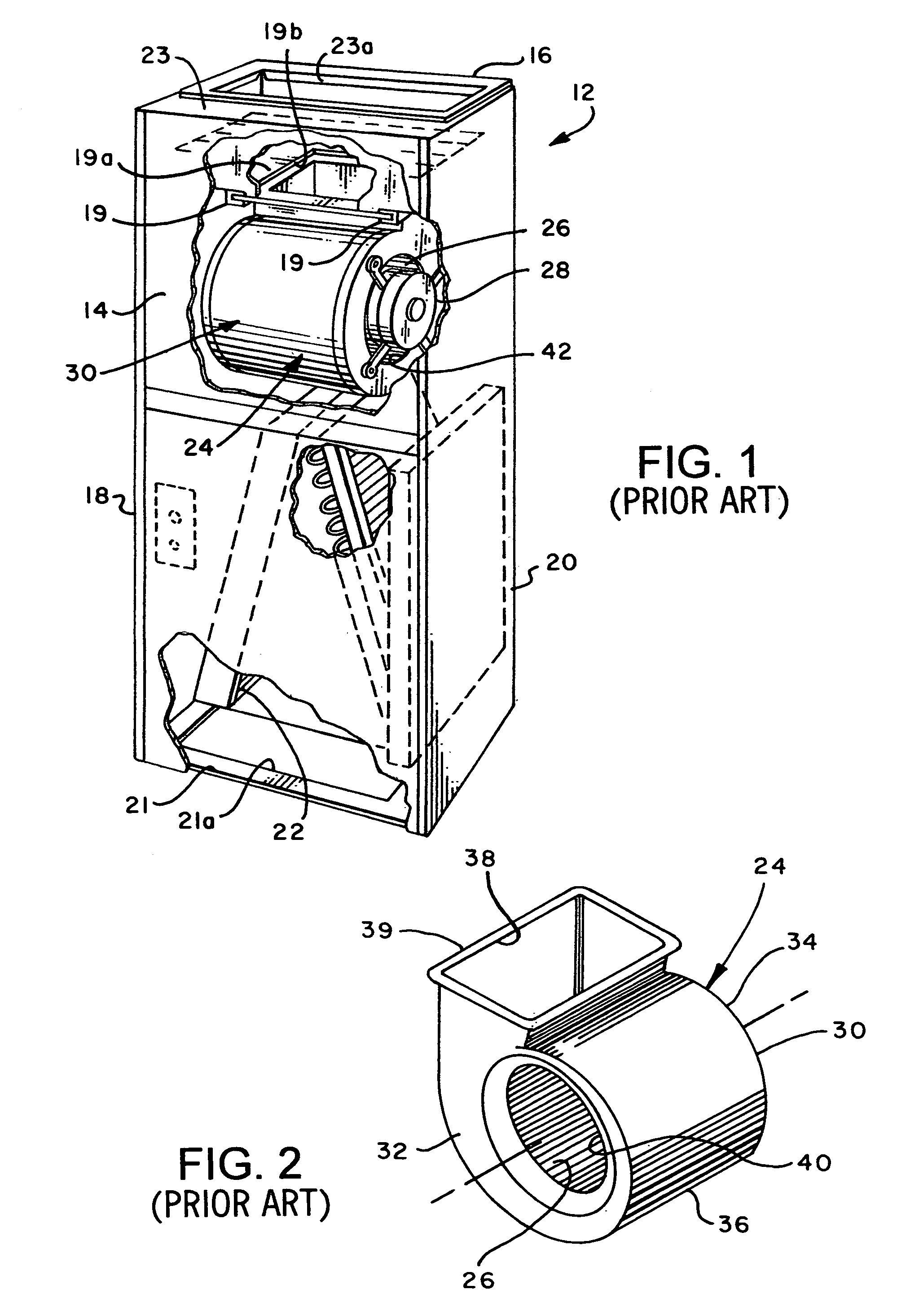
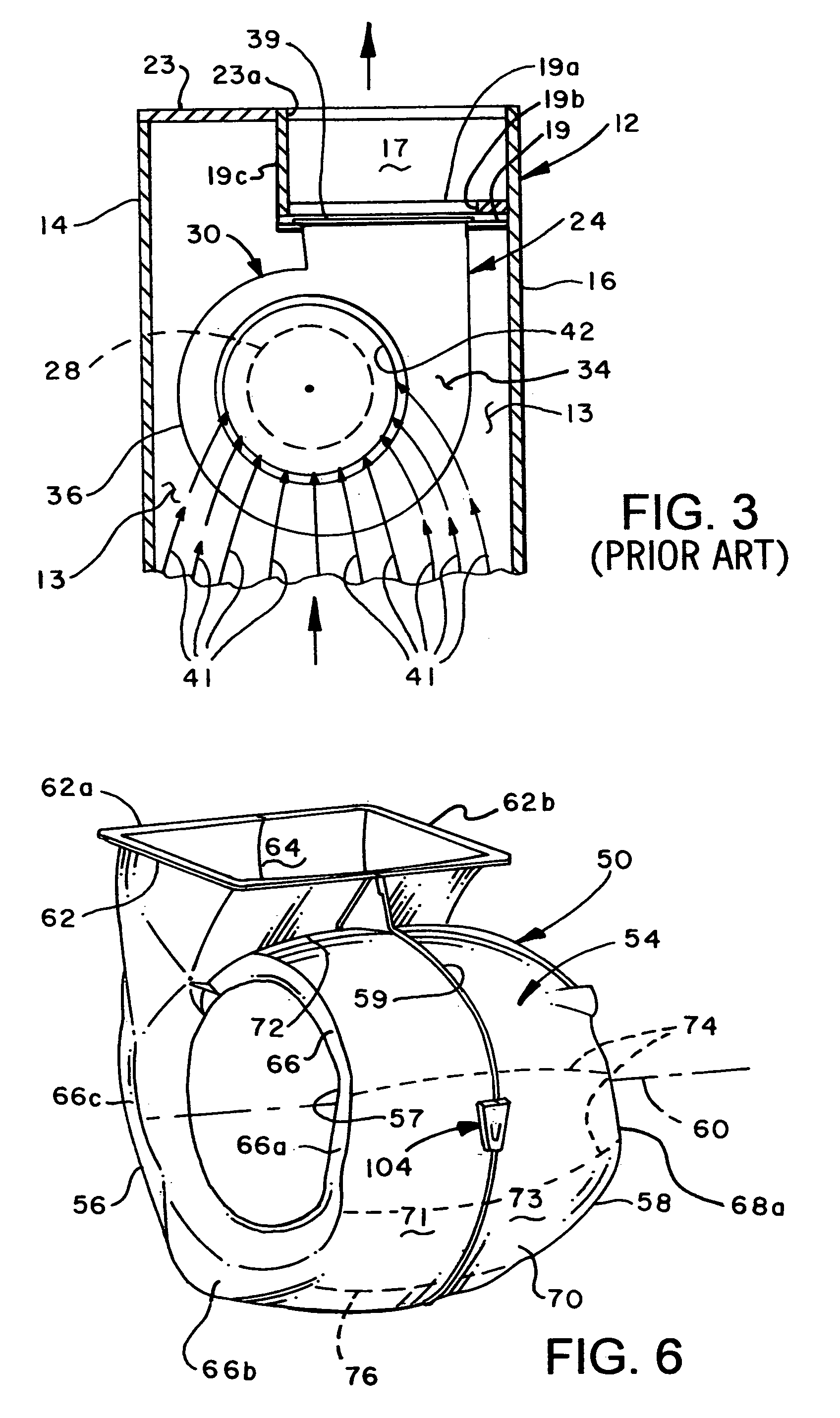
[0020]Referring to FIG. 1, there is illustrated an example of a prior art airhandling unit for an HVAC system comprising a generally rectangular metal cabinet 12 having a front wall 14, a back wall 16 and opposed sidewalls 18 and 20. A bottom wall 21 may have a suitable air inlet opening 21a therein for allowing air to enter the cabinet 12 and pass through a heat exchanger 22, such as a so-called A-frame air conditioning evaporator coil, as shown. Air is induced into the cabinet 12 by a centrifugal, electric motor driven blower 24 having a conventional centrifugal impeller 26, see FIG. 2, also, driven by a conventional electric motor 28, FIG. 1. Air is discharged from blower 24 into a plenum 17, FIG. 3, and then through an opening 23...


PUM


Abstract

An airhandling unit for an HVAC system includes a cabinet having an electric motor driven centrifugal blower disposed therein. The blower includes a scroll or volute type blower housing which may be formed of opposed releasably connectable housing parts. The blower housing parts include opposed sidewalls with axially extending compound curved portions which cooperate with an end wall which is configured to have portions which are not of substantially constant increasing radial distance from the blower impeller axis of rotation. However, a constantly increasing airflow cross-sectional flow area is provided within the blower housing for blower discharge air. The disposition of the blower housing sidewalls with respect to the cabinet walls provides improved airflow distribution for air flowing into the blower air inlet openings.

Description

CROSS-REFERENCE TO RELATED APPLICATION[0001]This application is a continuation-in-part of U.S. patent application Ser. No. 10 / 461,042, filed Jun. 13, 2003 now U.S. Pat. No. 7,014,422.BACKGROUND OF THE INVENTION[0002]Centrifugal airhandling blowers are widely used for circulating air in residential and commercial heating, ventilating and air conditioning (HVAC) systems. Electric motor driven centrifugal blowers or fans mounted in volute or scroll type blower housings are particularly widely used in HVAC systems wherein the blower housing is mounted in a cabinet which may also contain heat transfer equipment such as a refrigerant fluid heat exchanger or a furnace heat exchanger, for example.[0003]One problem faced by prior art airhandling blowers is the inability to expand the capacity of the blower within a given cabinet size beyond a certain blower housing size, since the physical dimensions of the blower housing of increased capacity prevent installation in a cabinet without redesi...

Claims


Application Information

Patent Timeline
Patent Type & Authority Patents(United States)
IPC IPC(8): F04D25/00F04D17/02F04D29/42F04D29/62F24F1/0053F24F7/007F24F13/20
CPCF04D17/02F04D29/424F04D29/626F24F1/0022F24F7/007F24F1/0007F24F2001/004F24F2013/205F24F1/005F24F1/0053
Inventor HANCOCK, STEPHEN S.
Owner TRANE INT INC
Why Eureka
Try Eureka