Multi-stage transmission
a transmission and multi-stage technology, applied in the direction of gearing details, gearing, transportation and packaging, etc., can solve the problems of unfavorable succession of gear stages, and achieve the effect of a greater gear spread
- Summary
- Abstract
- Description
- Claims
- Application Information
AI Technical Summary
Benefits of technology
Problems solved by technology
Method used
Image
Examples
first embodiment
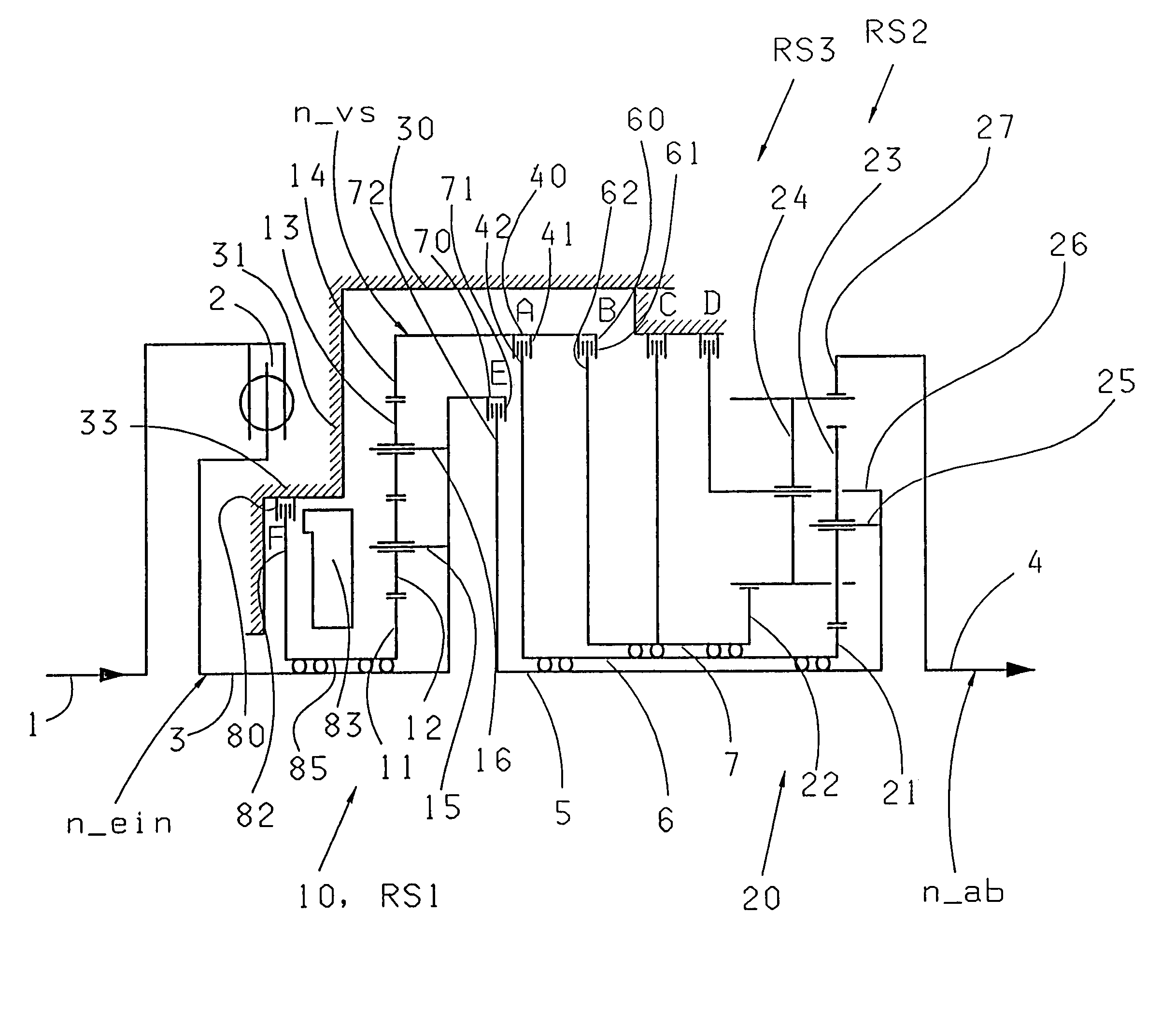
[0117]Using the exemplary component arrangement as shown in FIG. 13, FIGS. 14 and 15 show two embodiments for the arrangement of the servo apparatuses 43, 63 of the clutches A and B. As is to be seen in FIG. 14, in a first embodiment, proposed is, that the servo apparatus 63 of the clutch B—where the position of disks 61 of the clutch B is not changed, at least partially in the radial direction above the primary planetary gear set 10—onto which is to be placed that side of the primary planetary gear set 10 which is proximal to the principal planetary gear set 20, the position being axially in the direction of the principal planetary gear set and bordering on the clutch A. Advantageously, in this arrangement, a portion of the servo apparatus 63 of the clutch B borders directly on the predominately disk-like designed inner disk carrier 42 of the clutch A. An activation element of the servo apparatus 63 extends radially between the outer disk carrier 40, which forms the input element f...
second embodiment
[0121]In FIG. 15, presented as the spatial arrangement of the servo apparatuses 43, 63 of the clutches A, B, the proposal is made, which deviates from the previously described component arrangements in accordance with FIG. 13 and FIG. 14, that the respective disks 41, 61 of both clutches A, B are now to be activated from that side which is proximal to the support plate 35. The spatial position of the disks 41, 61, relative to the planetary gear sets and other shifting elements, is now at least essentially identical to FIGS. 13 and 14.
[0122]The spatial location and design of the outer disk carrier 60 of the clutch B, which are presented in FIG. 15, along with the spatial positioning of the servo apparatus 63 of the clutch B within the cylindrical outer disk carrier 60 were entirely taken over from FIG. 14. In the differences to FIG. 14 and as well to FIG. 13, provision has been made, that the servo apparatus 43 of the clutch A on that side of the disks 41 remote from the primary plan...
PUM
 Abstract
Description
Claims
Application Information
 - R&D
- Intellectual Property
- Life Sciences
- Materials
- Tech Scout
- Unparalleled Data Quality
- Higher Quality Content
- 60% Fewer Hallucinations
Browse by: Latest US Patents, China's latest patents, Technical Efficacy Thesaurus, Application Domain, Technology Topic, Popular Technical Reports.
© 2025 PatSnap. All rights reserved.Legal|Privacy policy|Modern Slavery Act Transparency Statement|Sitemap|About US| Contact US: help@patsnap.com


