Endoscopic visualization apparatus with different imaging systems

a visualization apparatus and imaging system technology, applied in the field of endoscopic visualization apparatus, can solve the problems of increased operation cost, inability to operate, and lengthen operation time, and achieve the effect of narrow overall design, improved orientation, and high resolution of observation of the tip

Inactive Publication Date: 2006-09-19
KARL STORZ GMBH & CO KG
View PDF19 Cites 126 Cited by
  • Summary
  • Abstract
  • Description
  • Claims
  • Application Information

AI Technical Summary

Benefits of technology

[0033]the image of larger aperture angle can serve the surgeon as overall image for the purpose of better orientation in the operating space, while the image field of smaller aperture angle, and thus a larger image, permits a more highly resolving observation of the tip of the operating instrument and of the tissue located in its vicinity.
[0034]In a preferred

Problems solved by technology

Both the setting of a zoom objective, the axial displacement of the endoscope and the changing of various endoscopes constitute additional manipulations, and thus an additional outlay, and so the operating times are lengthened and the costs of operations are raised because of additional visualization apparatuses.
Apart from this stereoscopic information, it is not possible in the case of the two known visualization apparatuses previously ment

Method used


Image

  • Endoscopic visualization apparatus with different imaging systems
  • Endoscopic visualization apparatus with different imaging systems
  • Endoscopic visualization apparatus with different imaging systems

Examples


Embodiment Construction

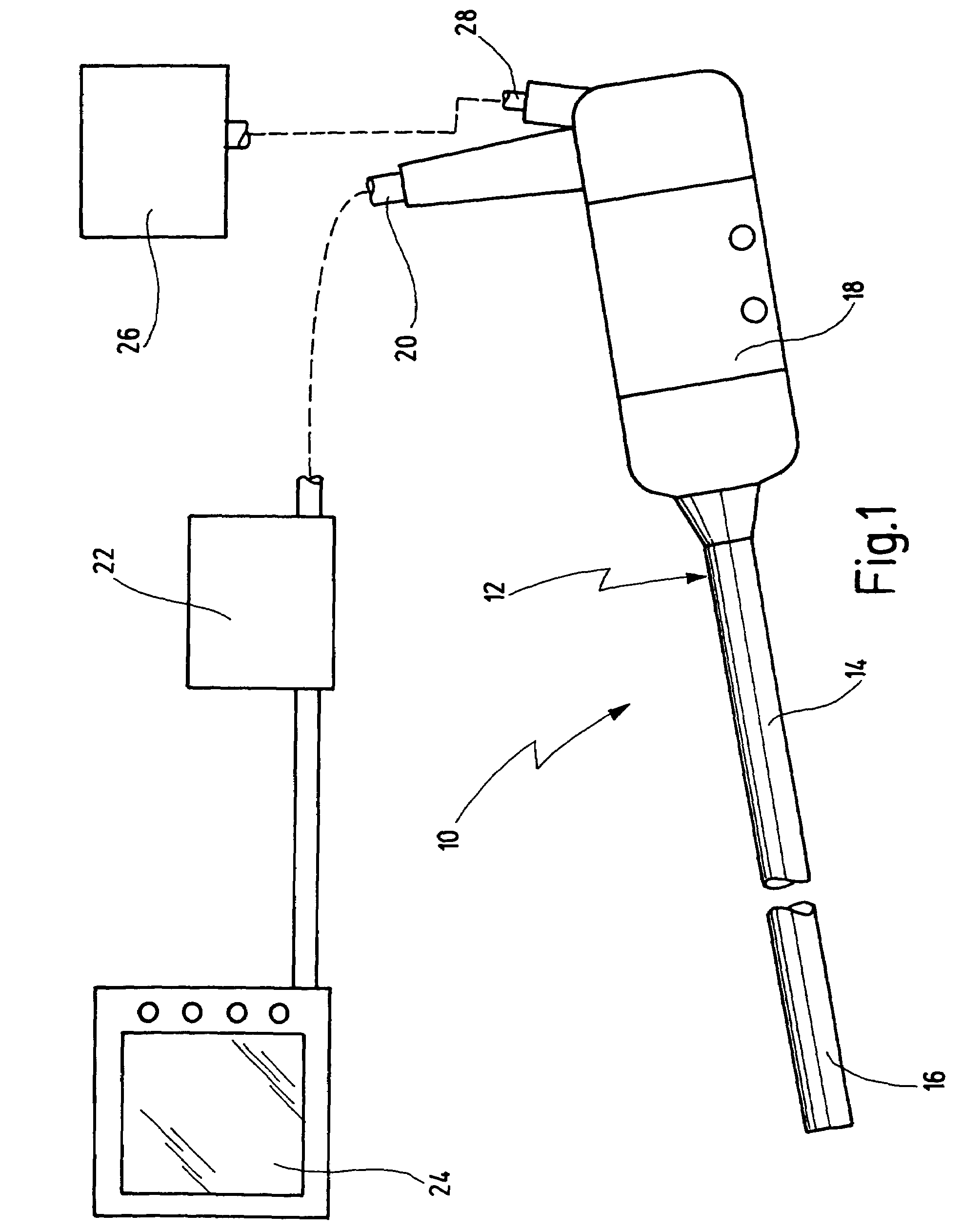
[0045]An endoscopic visualization apparatus provided with the general reference numeral 10 is illustrated in FIG. 1. The endoscopic visualization apparatus 10 is designed in the form of an endoscope 12 in the exemplary embodiment shown.

[0046]The endoscopic visualization apparatus 10 in the form of the endoscope 12 is used in the field of minimally invasive surgery.

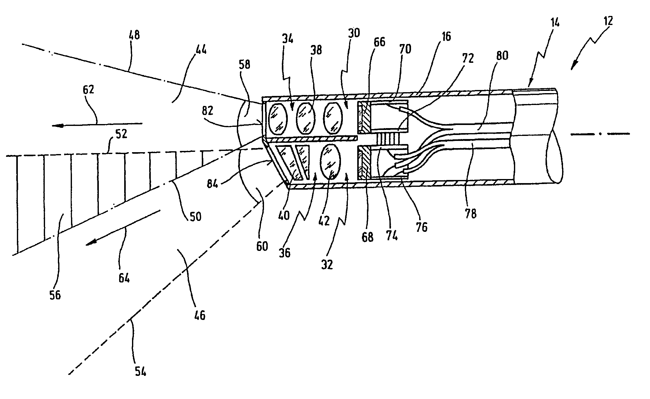
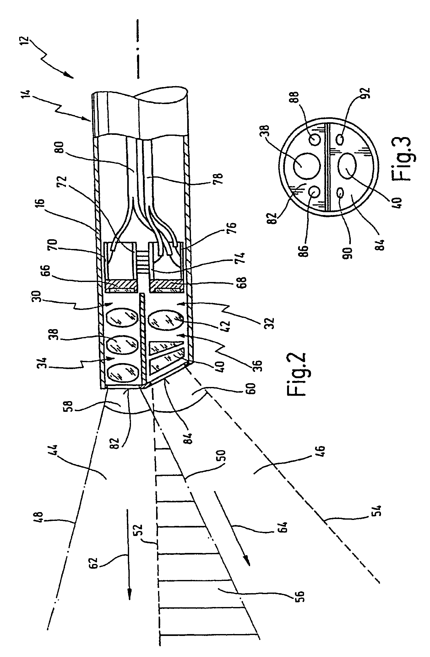
[0047]The endoscope 12 has an elongated shaft whose distal end section or distal end is provided with the reference numeral 16.

[0048]In the exemplary embodiment shown, the shaft 14 is designed to be rigid overall, but the present invention can equally well be used in the case of a flexible endoscope with a correspondingly flexible shaft.

[0049]The endoscope 12 is designed, furthermore, as a video endoscope and therefore does not have an eyepiece at the proximal end of the shaft 14, but a handpiece 18. A cable 20 leads from the handpiece 18 for the purpose of electric signal transmission to an image processing unit 22 which ...


PUM


Abstract

An endoscopic visualization apparatus has a first imaging system and at least one second imaging system, a first image field being covered by the first imaging system, and a second image field being covered by the second imaging system. The first imaging system and the second imaging system are arranged in a common housing. The first imaging system and the second imaging system are significantly different with regard to at least one optical parameter, and the first image field and the at least one second image field overlap one another only partially.

Description

CROSS-REFERENCE TO PENDING APPLICATION[0001]The present application is a continuation of pending international patent application PCT / EP 02 / 03519 filed on Mar. 28, 2002 which designates the United States and which claims priority of German patent application 101 16 056.9 filed on Mar. 30, 2001.BACKGROUND OF THE INVENTION[0002]The invention relates to an endoscopic visualization apparatus having a first imaging system and having at least one second imaging system, a first image field being covered by the first imaging system, and a second image field being covered by the second imaging system, and the imaging systems being arranged in a common housing.[0003]An endoscopic visualization apparatus of the type mentioned at the beginning is used, for example, as an observation system for medical purposes in what is termed minimally invasive surgery. In the case of standard operations such as, for example, laparoscopic cholecystectomy, access is usually made to the abdominal cavity via thr...

Claims


Application Information

Patent Timeline
IPC IPC(8): A61B1/05A61B1/045A61B1/00
CPCA61B1/00096A61B1/00181
Inventor IRION, KLAUS M.STORZ, KARL CHRISTIAN
Owner KARL STORZ GMBH & CO KG
Why Eureka
Try Eureka