
Anastomosis device having at least one frangible member

a technology of anastomosis device and frangible member, which is applied in the direction of prosthesis, surgical staples, blood vessels, etc., can solve the problems of reducing affecting the survival rate of patients, and requiring a high level of surgical skill, so as to minimize thrombosis or restenosis, the effect of very rapid operation

Inactive Publication Date: 2006-09-19
AESCULAP AG
View PDF301 Cites 28 Cited by
  • Summary
  • Abstract
  • Description
  • Claims
  • Application Information

AI Technical Summary

Benefits of technology

The invention is about anastomotic stents for connecting a graft vessel to a target vessel. The stents come in different sizes and can be used in a variety of procedures such as coronary artery bypass grafting. The stents have a cylindrical body with a deformable section that forms a flange that applies an axial force against the target vessel wall to secure the stent. The stents can be longitudinally collapsed to position the flanges against the target vessel wall. The invention also includes applicators for inserting and securing the stents to the target vessel. The technical effects of the invention are improved anastomotic procedures and better outcomes for patients.

Problems solved by technology

The treatment, known as coronary artery bypass grafting (CABG), can be highly traumatic to the patient's system.
The suturing procedure is a time consuming, difficult process requiring a high level of surgical skill.
As a result, in less invasive approaches which provide only limited access to the patient's vessels, some of the major coronary vessels cannot be reached adequately, which can result in incomplete revascularization and a resulting negative effect on patient survival.
Moreover, certain target vessels, such as heavily calcified coronary vessels, vessels having a very small diameter of less than about 1 mm, and previously bypassed vessels, may make the suturing process difficult or impossible, so that a sutured anastomosis is not possible.
Additionally, a common problem with CABG has been the formation of thrombi and atherosclerotic lesions at and around the grafted artery, which can result in the reoccurrence of ischemia.
Moreover, second operations necessitated by the reoccurrence of arterial occlusions are technically more difficult and risky due to the presence of the initial bypass.
For example, surgeons have found it difficult to saw the sternum in half during the next operation without damaging the graft vessels from the first bypass which are positioned behind the sternum.

Method used


Image

  • Anastomosis device having at least one frangible member
  • Anastomosis device having at least one frangible member
  • Anastomosis device having at least one frangible member

Examples


Embodiment Construction

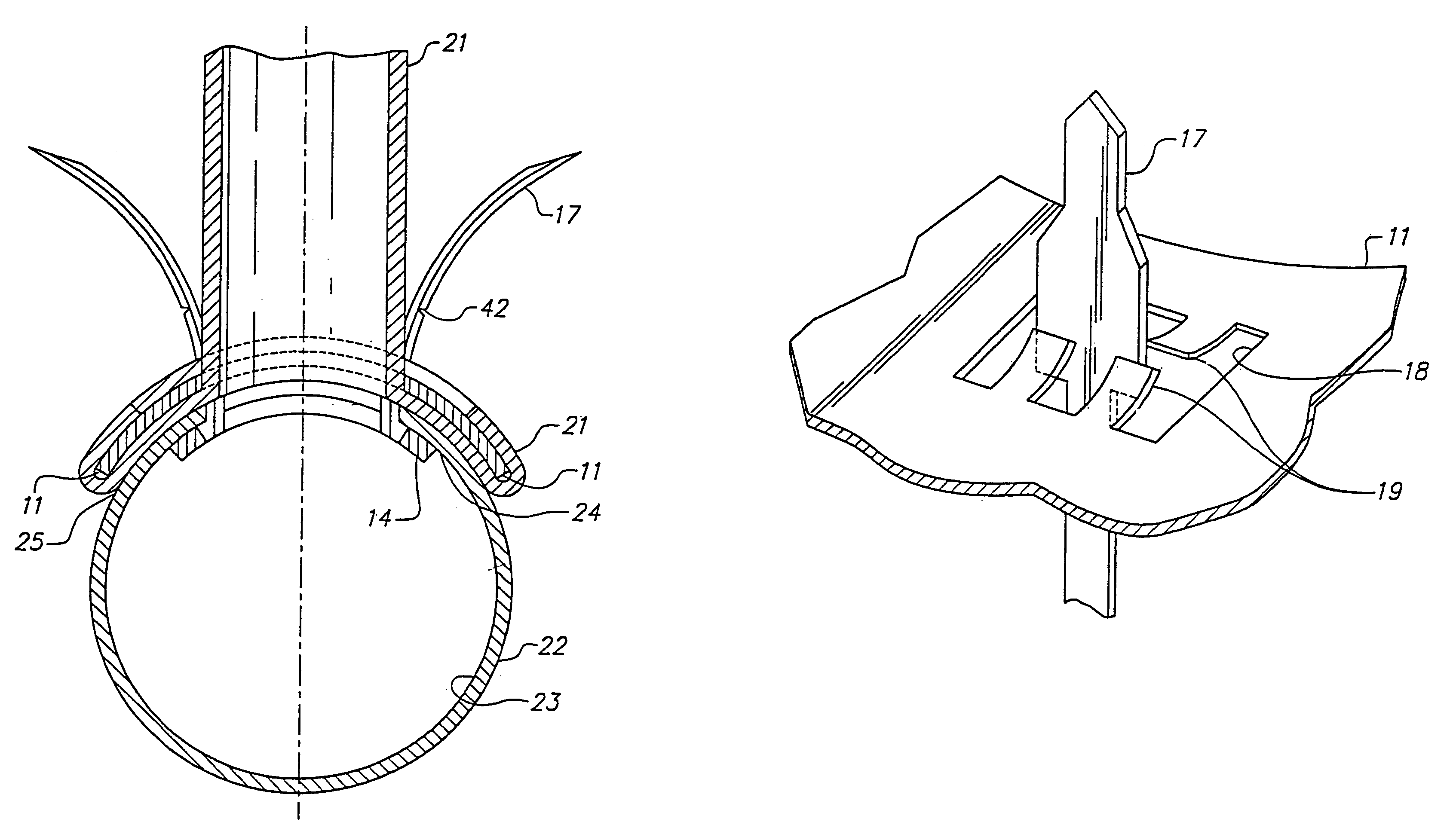
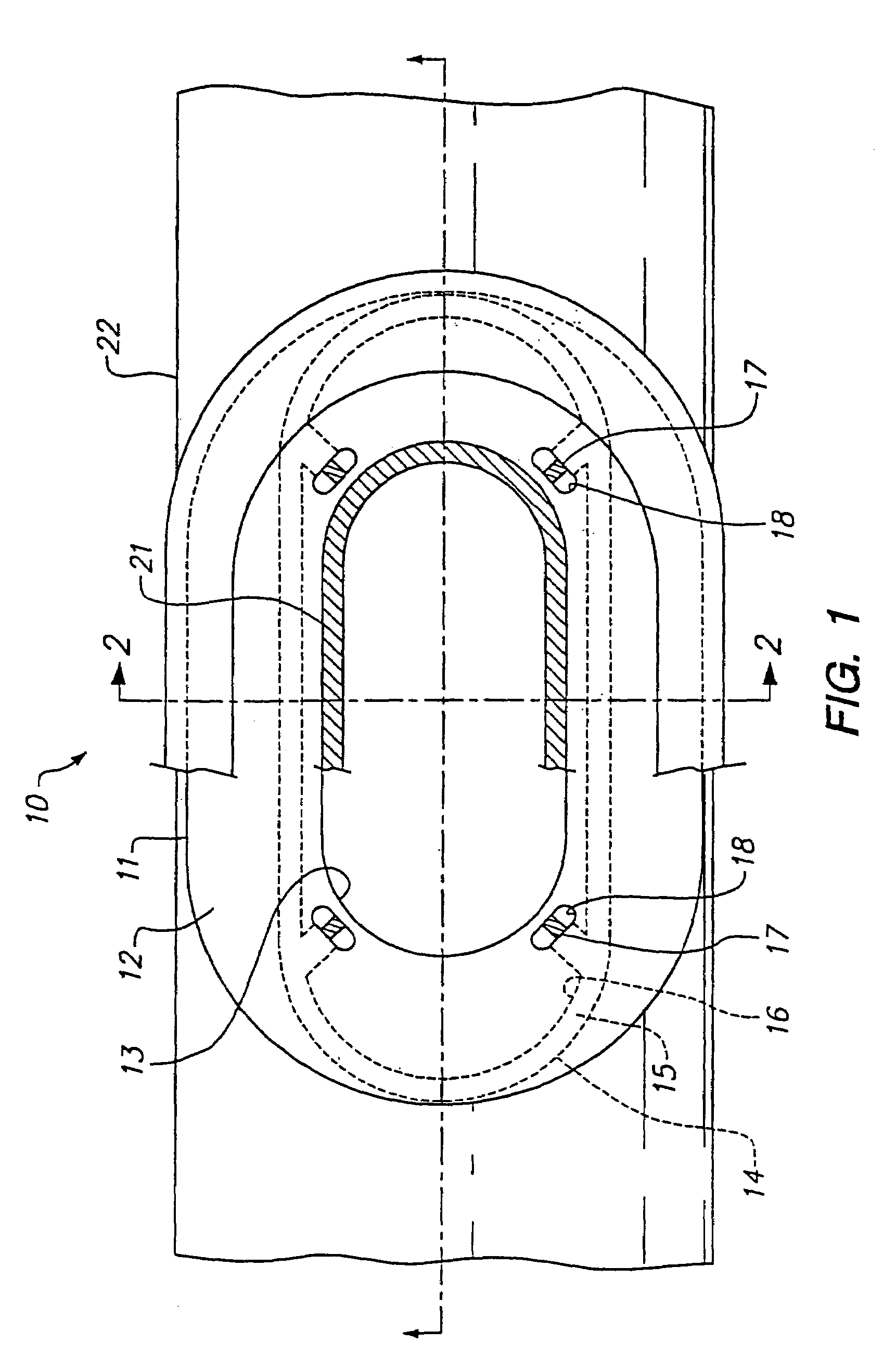
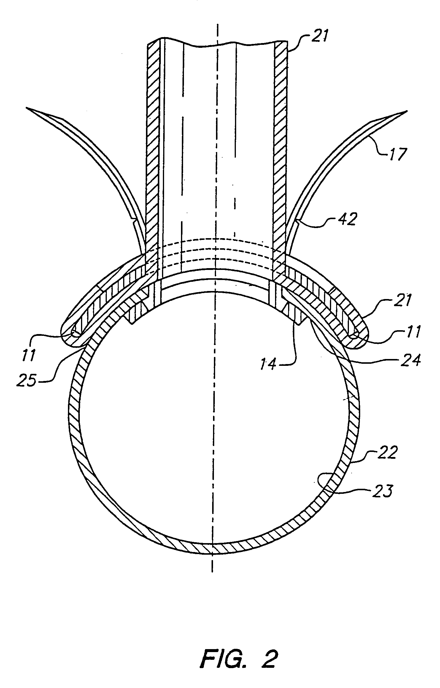
[0056]A presently preferred embodiment of the small vessel stent 10 of the invention, for connecting one end of a graft vessel to a small target vessel, is illustrated in FIG. 1. The small vessel stent 10 comprises an outer flange 11 having a body 12 which defines an opening 13 configured to receive the end of the graft vessel 21, and an inner flange 14 having a body 15 which defines an opening 16. The inner flange is configured to be connected to the outer flange, with the openings 13, 16 at least in part aligned. In the embodiment illustrated in FIG. 1, prongs 17 on the inner flange are configured to be received within small openings 18 in the outer flange, to thereby connect the flanges together. As best illustrated in FIG. 2, showing a transverse cross section of the small vessel stent 10 shown in FIG. 1, taken along lines 2—2, the inner flange 14 is configured to be positioned within a lumen 23 of the target vessel 22 against an inner surface 24 of the target vessel, and the ou...


PUM


Abstract

An anastomosis device may include at least one first element connectible to at least one second element, where at least one first element is frangible. At least one second element may include at least one opening therethrough, where each opening receives a corresponding first element. At least one deflectable tab may extend into at least one opening to engage a corresponding first element.

Description

[0001]This application is a continuation of U.S. patent application Ser. No. 10 / 197,352, filed on Jul. 16, 2002, now U.S. Pat. No. 6,805,708 which in turn is a continuation of U.S. patent application Ser. No. 09 / 778,003, filed Feb. 7, 2001, now U.S. Pat. No. 6,497,710, issued on Dec. 24, 2002, which in turn is a divisional of U.S. patent application Ser. No. 09 / 133,185, filed Aug. 12, 1998, now U.S. Pat. No. 6,206,913, issued on Mar. 27, 2001, all of which are incorporated by reference in their entirety.BACKGROUND[0002]This invention generally relates to devices for performing vascular anastomosis.[0003]Vascular anastomosis, in which two vessels within a patient are surgically joined together to form a continuous channel, are required for a variety of conditions including coronary artery disease, diseases of the great and peripheral vessels, organ transplantation, and trauma. For example, in coronary artery disease (CAD), an occlusion or stenosis in a coronary artery interferes with...

Claims


Application Information

Patent Timeline
Patent Type & Authority Patents(United States)
IPC IPC(8): A61B17/08A61B17/064A61B17/11A61B17/115A61B19/00A61F2/06
CPCA61B17/11A61B17/115A61F2/064A61B17/064A61B2017/0641Y10S623/903A61B2017/1135A61B2019/307A61B2017/1107A61B2090/037
Inventor YENCHO, STEPHEN A.HAUSEN, BERNARD A.
Owner AESCULAP AG
Learn More