

Feed mixer for a partial oxidation reactor
a partial oxidation and gas feed technology, applied in the direction of liquid-gas reaction process, indirect carbon-dioxide mitigation, process and machine control, etc., can solve the problems of uneconomical formation, transportation technology challenges, and final cost of natural gas
Active Publication Date: 2006-09-19
PHILLIPS 66 CO
View PDF71 Cites 35 Cited by
- Summary
- Abstract
- Description
- Claims
- Application Information
AI Technical Summary
Benefits of technology
[0020]Thus, the present invention comprises a combination of features and advantages that enable it to substantially increase the efficiency of mixing natural gas and oxygen to feed a catalytic partial oxidation process. These and various other characteristics and advantages of the present invention will be readily apparent to those skilled in the art upon reading the following detailed description of the preferred embodiments of the invention and by referring to the accompanying drawings.
Problems solved by technology
Wells that provide natural gas are often remote from locations with a demand for the consumption of the natural gas.
This transportation presents technological challenges due in part to the large volume occupied by a gas.
However, this contributes to the final cost of the natural gas and is not economical for formations containing small amounts of natural gas.
However, current environmental concerns and regulations discourage or prohibit this practice.
Further, naturally occurring sources of crude oil used for liquid fuels such as gasoline, jet fuel, kerosene, and diesel fuel have been decreasing and supplies are not expected to meet demand in the coming years.
The same feed conditions that are conducive to efficient operation of the partial oxidation process, however, could lead to reactions that are less desirable, and possibly even hazardous, such as the ignition and combustion of the feedstock.
One problem with such mixing processes is that heated mixtures of oxygen and methane, at pressures of interest for syngas production, are highly reactive and can be explosive.
This technique often involves placing the mixing apparatus in close proximity to the reactor, which may make maintenance of the mixing apparatus difficult and requires that the mixer be designed to withstand the extreme environment of a partial oxidation reactor.
Another problem encountered in the design of these types of mixers is that high concentrations of oxygen, or oxygen rich gas, impacting components of the mixer at high velocities can cause damage to components of the mixer.
This high speed contact can lead to oxygen impingement and a thermochemical reaction that may damage, and even destroy, components of the mixer.
Method used
View moreImage
Smart ImageViewing Examples

Examples
second embodiment
[0024]FIG. 3 is a cross-sectional view of a reactor inlet section
third embodiment
[0025]FIG. 4 is a cross-sectional view of a reactor inlet section;
fourth embodiment
[0026]FIG. 5 is a cross-sectional view of a reactor inlet section; and
[0027]FIG. 6 is an elevation view of the mixing plate of FIG. 5.
Login to View More PUM
| Property | Measurement | Unit |
|---|---|---|
| angle | aaaaa | aaaaa |
| angle | aaaaa | aaaaa |
| angle | aaaaa | aaaaa |
Abstract
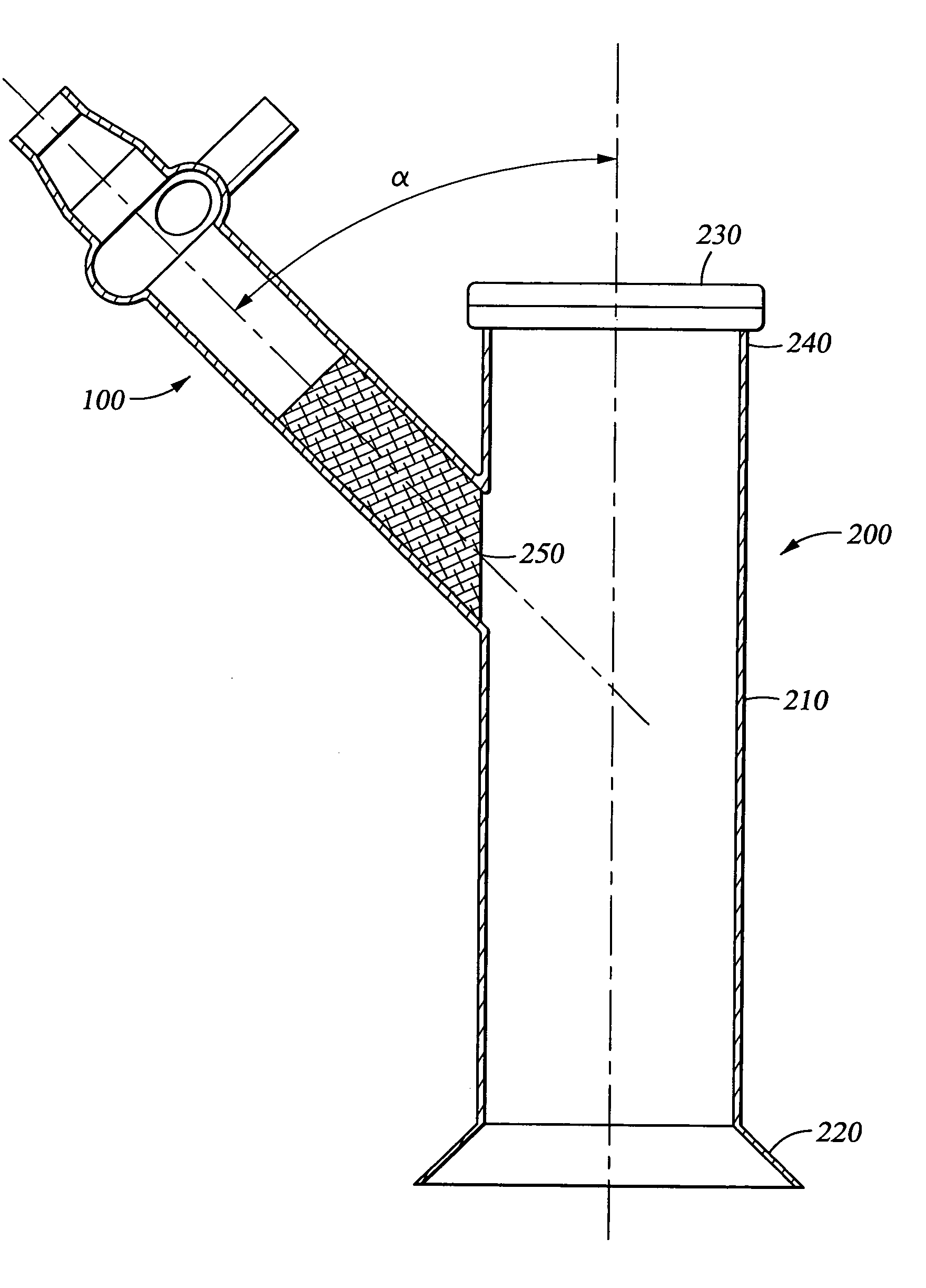
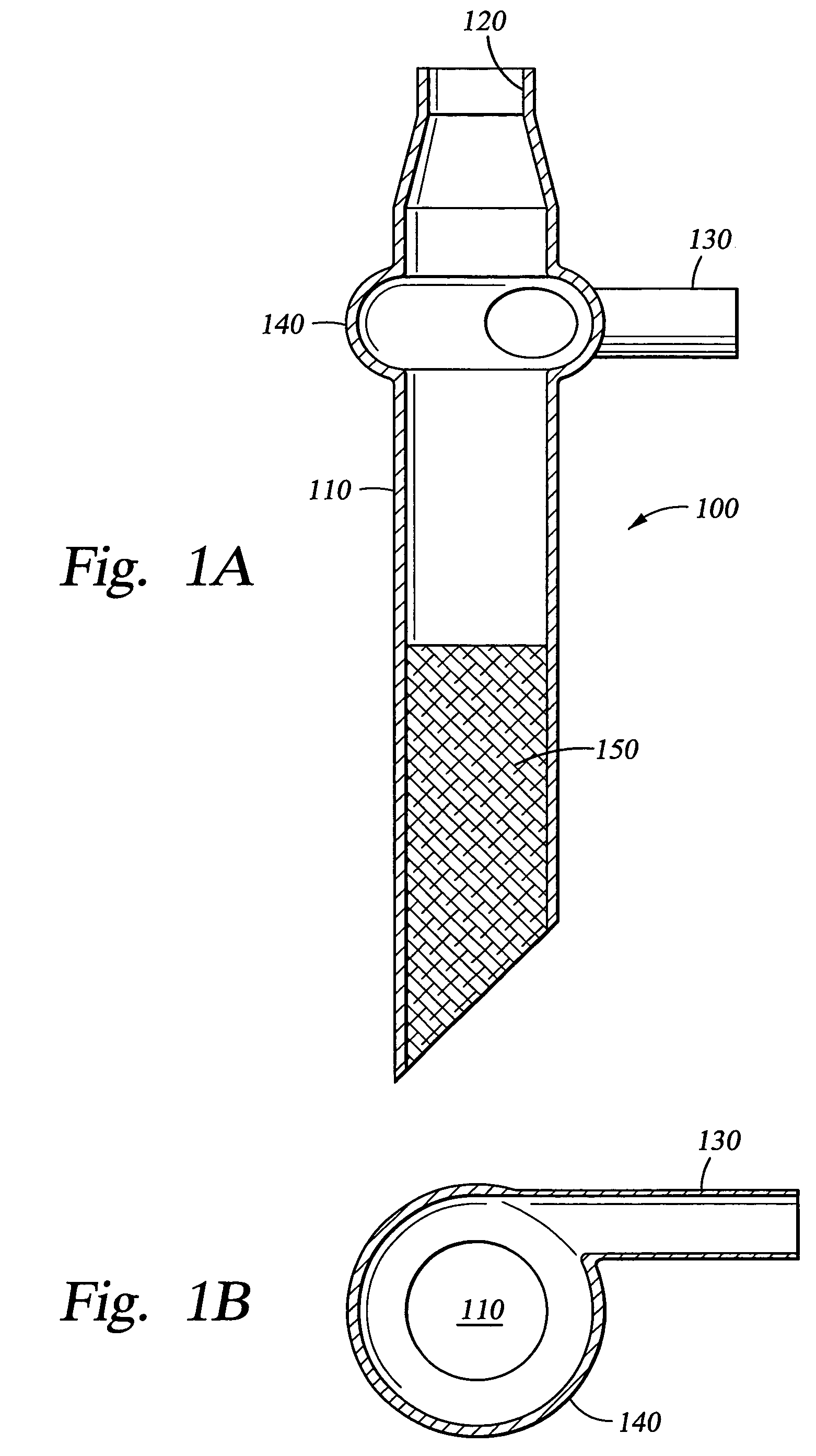
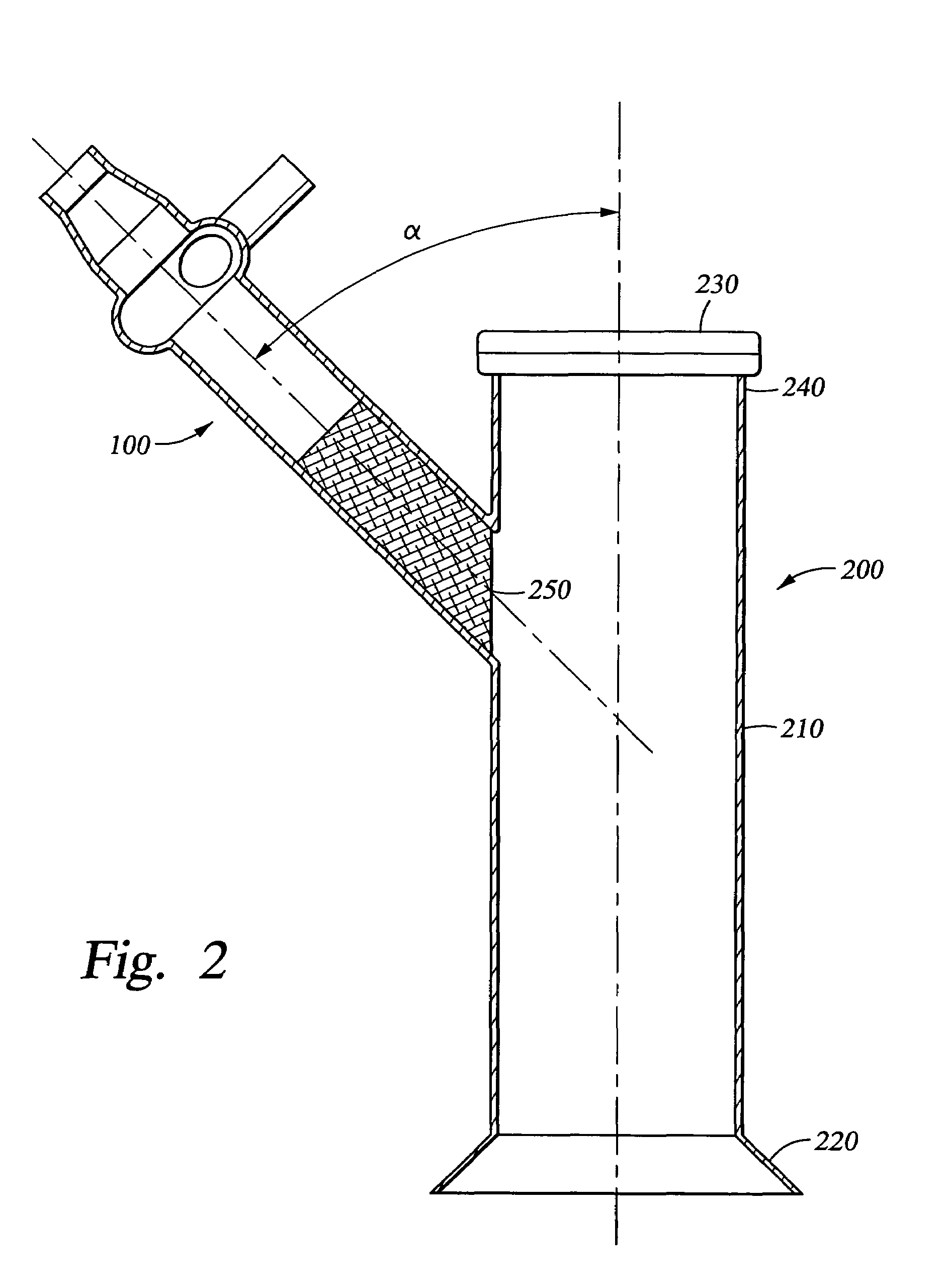
Methods and apparatus for mixing a plurality of gases, preferably a fuel and an oxidant. The preferred embodiments are characterized by methods and apparatus for mixing at least a methane-containing gas and an oxygen-containing gas, preferably natural gas and molecular oxygen. The preferred embodiments of the present invention include a mixing section having a centrifugal mixer with a tangential inlet where the mixed gases are then injected at an angle into the reactor section. The oxidant and the fuel are mixed by the tangential motion of the fuel to form a reactant gas that then flows through a permeable mixing material that is also disposed within the chamber. The reactant gas injected at an angle into a reactor inlet chamber provides a substantially unobstructed path between the reactor and a pressure relief device.
Description
CROSS-REFERENCE TO RELATED APPLICATIONS[0001]Not applicable.STATEMENT REGARDING FEDERALLY SPONSORED RESEARCH OR DEVELOPMENT[0002]Not applicable.TECHNICAL FIELD OF THE INVENTION[0003]The present invention relates generally to methods and apparatus for mixing gases. More specifically, the present invention relates to methods and apparatus for mixing a feed gas to supply a catalytic partial oxidation process.BACKGROUND OF THE INVENTION[0004]Natural gas, found in deposits in the earth, is an abundant energy resource. For example, natural gas commonly serves as a fuel for heating, cooking, and power generation, among other things. The process of obtaining natural gas from an earth formation typically includes drilling a well into the formation. Wells that provide natural gas are often remote from locations with a demand for the consumption of the natural gas.[0005]Thus, natural gas is conventionally transported large distances from the wellhead to commercial destinations in pipelines. Th...
Claims
Login to View More Application Information
Patent Timeline
 Patent Type & AuthorityPatents(United States)
IPC IPC(8): B01J19/26C01B3/32B01F5/00B01F5/04B01F5/06B01J4/00B01J8/02B01J19/24C01B3/38F23D14/64F23D14/70F23L7/00
CPCB01F5/0057B01F5/0475B01F5/0691B01J8/025B01J8/0278B01J19/2485C01B3/386F23D14/64F23D14/70F23L7/007B01F5/0473Y02E20/344B01J2208/00849C01B2203/0261C01B2203/061C01B2203/062C01B2203/1276F23D2203/105Y02E20/322Y02E20/34B01F25/10B01F25/3142B01F25/3141B01F25/4522
InventorMCGEE, KENNETH SCOTT
OwnerPHILLIPS 66 CO