Eureka AIR delivers breakthrough ideas for toughest innovation challenges, trusted by R&D personnel around the world.

Micro-electromechanical system and method for production thereof

a micro-electromechanical and micro-electromechanical technology, applied in the direction of contacts, basic electric elements, relays, etc., can solve the problems of difficult to achieve high reproducibility, achieve low switching voltage, improve switchability, and increase the effect of electrostatic force of attraction

Inactive Publication Date: 2006-09-19
ABB RES LTD
View PDF9 Cites 8 Cited by
  • Summary
  • Abstract
  • Description
  • Claims
  • Application Information

AI Technical Summary

Benefits of technology

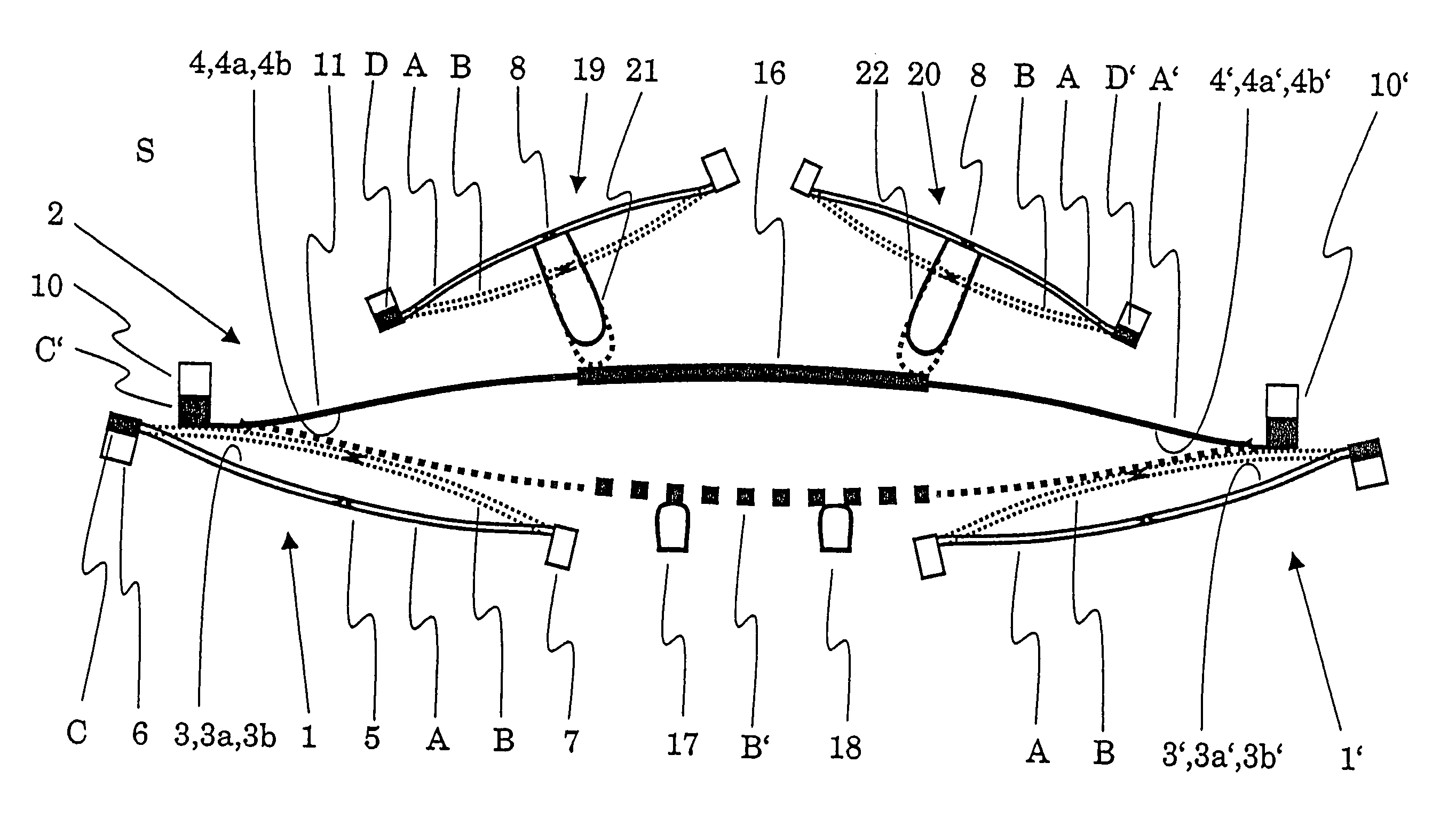
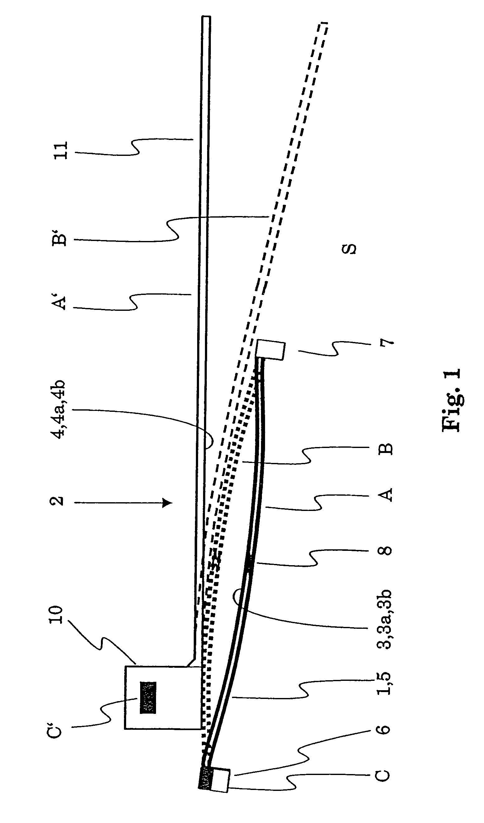
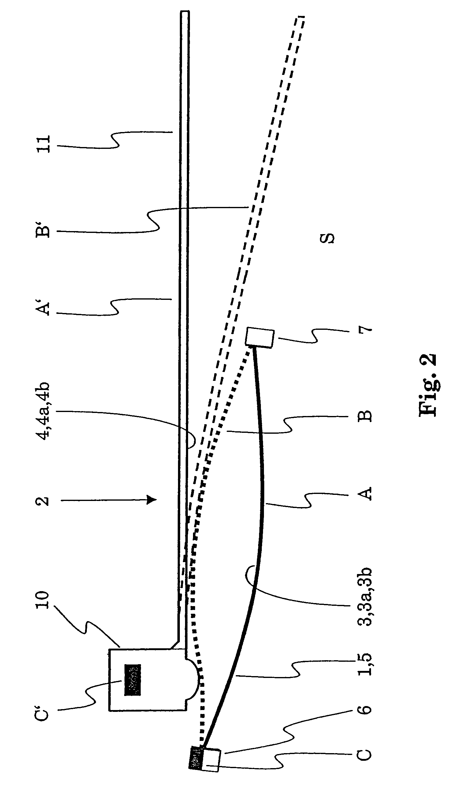
[0025]Thus, a first micro-element switchable between the two stable positions, initial position and working position, is used in conjunction with a second micro-element such that after switching from the initial position to the working position, the first micro-element has a shorter distance from the second micro-element than in the initial position. Both micro-elements are connected to the substrate and produced using a structuring method. Said shorter distance in the working position is, according to the invention, shorter than a minimal distance between the two micro-elements characteristic of the structuring method.
[0028]It is thus made possible to produce electrostatically operating actuators whose electrostatically switchable electrodes (electrode and counter-electrode) contact one another. The small or vanishing electrode gaps thereby achieved have an improved switchability in consequence. It is possible to switch the actuator at very low switching voltages.
[0029]In a further advantageous embodiment of the subject matter of the invention, the first micro-element is additionally constructed such that it contains a matched counter-electrode which is matched to the shape of the second micro-element: the matched counter-electrode is shaped such that in the switch-on position of the second micro-element the matched counter-electrode and the second micro-element overlap over a large area in the area of said contact points. In the switch-on position of the second micro-element the matched counter-electrode and the second micro-element thus nestle up to one another. A maximisation of the surfaces between which the electrostatic forces of attraction act is thereby achieved which results in higher electrostatic forces of attraction and thus improved switchability. It is thus possible to switch the actuator at very low switching voltages.
[0030]In a further advantageous embodiment said matched counter-electrode additionally comprises a second section which is set back in a step shape with respect to the section of the counter-electrode nestling up to the second micro-element. In the switch-on position of the second micro-element, this second section of the matched counter-electrode and the second micro-element enclose a gap. In this way, a force which the second micro-element can exert in its switch-on position can be tailored and selected to be very large by suitably dimensioning the length, width and height of the gap. The force which can be selected to be large in this fashion can, for example, be a contact force of the second micro-element on one or two electric contacts which contact the second micro-element in its switch-on position whereby a more secure electrical contact can be produced.
[0033]In particular, in a preferred embodiment the movable part of the second micro-element is elastically deformable by switching the first micro-element from the initial position into the working position. It is thereby possible to achieve voltageless closed connections.

Problems solved by technology

In terms of production technology, it is not easy to achieve a high reproducibility of a curvature of the contacts thus produced and therefore of the contact spacings in the rest state (opened).

Method used


Image

  • Micro-electromechanical system and method for production thereof
  • Micro-electromechanical system and method for production thereof
  • Micro-electromechanical system and method for production thereof

Examples


Embodiment Construction

[0017]It is thus the object of the invention to provide a micro-electromechanical system (MEMS) of the type specified initially which makes it possible to achieve a more flexible MEMS design. In particular, an improved switchability and new functionalities should be made possible. This object is solved by an MEMS having the features of claim 1.

[0018]Furthermore, it is an object of the invention to provide an improved method for MEMS manufacture. This object is solved by a method having the features of claim 21.

[0019]Improved switchability can, for example, mean that a switching process can be triggered at lower switching voltages. New functionalities can, for example, mean realising voltageless closed connections or microrelays with both voltageless open and voltageless closed connections.

[0020]The MEMS according to the invention comprises a substrate as well as a first micro-element and a second micro-element, wherein[0021]the first micro-element and the second micro-element are co...


PUM


Abstract

A micro-electromechanical system comprises a substrate (S) and at least two micro-elements (1, 2) of which a first is bistably switchable. The micro-elements (1, 2) have faces (3a, 4a) facing one another, which are produced by a structuring method and thereby initially have at least one minimal distance from one another characteristic of the structuring method. The first micro-element (1) is then switched to the other stable state (B) whereby the distance between the faces (3a, 4a) facing one another is smaller than the characteristic minimal distance for the structuring method. The micro-electromechanical system can be constructed as an electrostatically actuatable microswitch with improved switchability. Laterally and horizontally operating micro-electromechanical systems with new functionality and current-free closed relays can be implemented.

Description

TECHNICAL FIELD[0001]The invention relates to the field of micro-electromechanical systems, especially[0002]to a micro-electromechanical system according to the preamble of claim 1 and[0003]to a method for manufacturing such a micro-electromechanical system according to the preamble of claim 21.PRIOR ART[0004]Such a micro-electromechanical system (MEMS) forming the preamble of claims 1 and 21 and a corresponding method are known, for example, from DE 198 00 189 A1. A micromechanical switch is described there, which comprises a flat support substrate, a contact piece positioned on the support substrate, a mobile electrode and a counter-electrode fixedly connected to the support substrate. The mobile electrode has a free end and a fixed end connected to the support substrate. The mobile electrode and the counter-electrode have surfaces facing one another. By means of electrostatic forces of attraction between these mutually facing surfaces, the mobile electrode can be bent, that is el...

Claims


Application Information

Patent Timeline
Patent Type & Authority Patents(United States)
IPC IPC(8): H01L27/14H01H59/00H01L23/34
CPCH01H59/0009H01H2001/0042B33Y80/00
Inventor STRUMPLER, RALF
Owner ABB RES LTD
Why Eureka
Eureka Blog
Learn More