Flywheel system with synchronous reluctance and permanent magnet generators

a flywheel and generator technology, applied in the field of electromechanical arts and energy storage systems, can solve the problems of flywheel internal electrical loads being deprived of the electric power required to complete a normal flywheel shutdown, and the usable electric output of flywheels being depleted

Active Publication Date: 2006-09-19
BEAVER AEROSPACE & DEFENSE
View PDF12 Cites 15 Cited by
  • Summary
  • Abstract
  • Description
  • Claims
  • Application Information

AI Technical Summary

Problems solved by technology

To the extent that a protracted power outage occurs and the flywheel's usable electric output is depleted by the external electric network, the flywheel's internal electrical loads may be deprived of the electric power required to complete a normal flywheel shutdown.
Supplying electric loads internal to the flywheel system during coast down presents a particular problem when the flywheel's electric generator has a minimum operating speed as is typical of inductive generators.

Method used


Image

  • Flywheel system with synchronous reluctance and permanent magnet generators
  • Flywheel system with synchronous reluctance and permanent magnet generators
  • Flywheel system with synchronous reluctance and permanent magnet generators

Examples


first embodiment

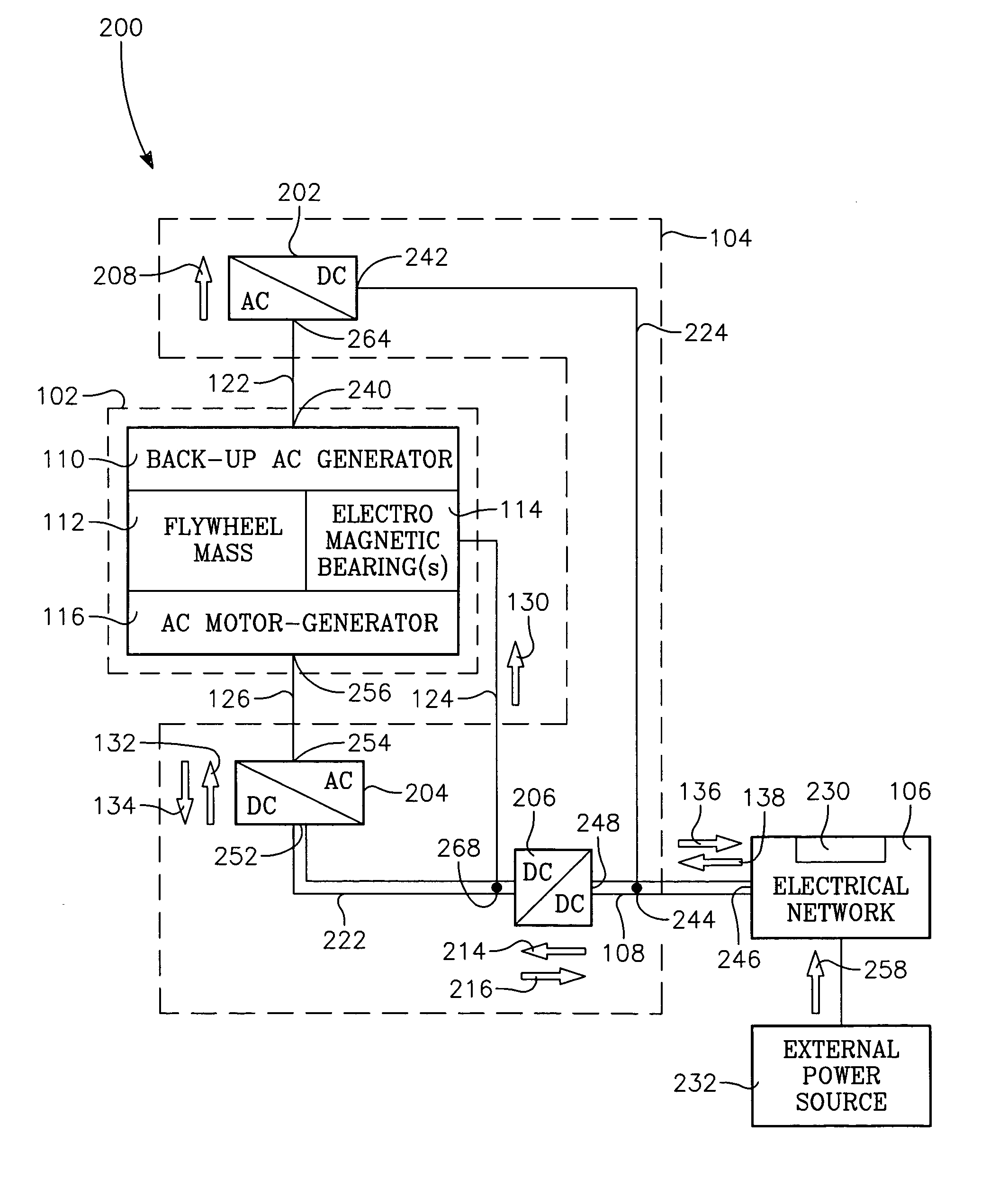
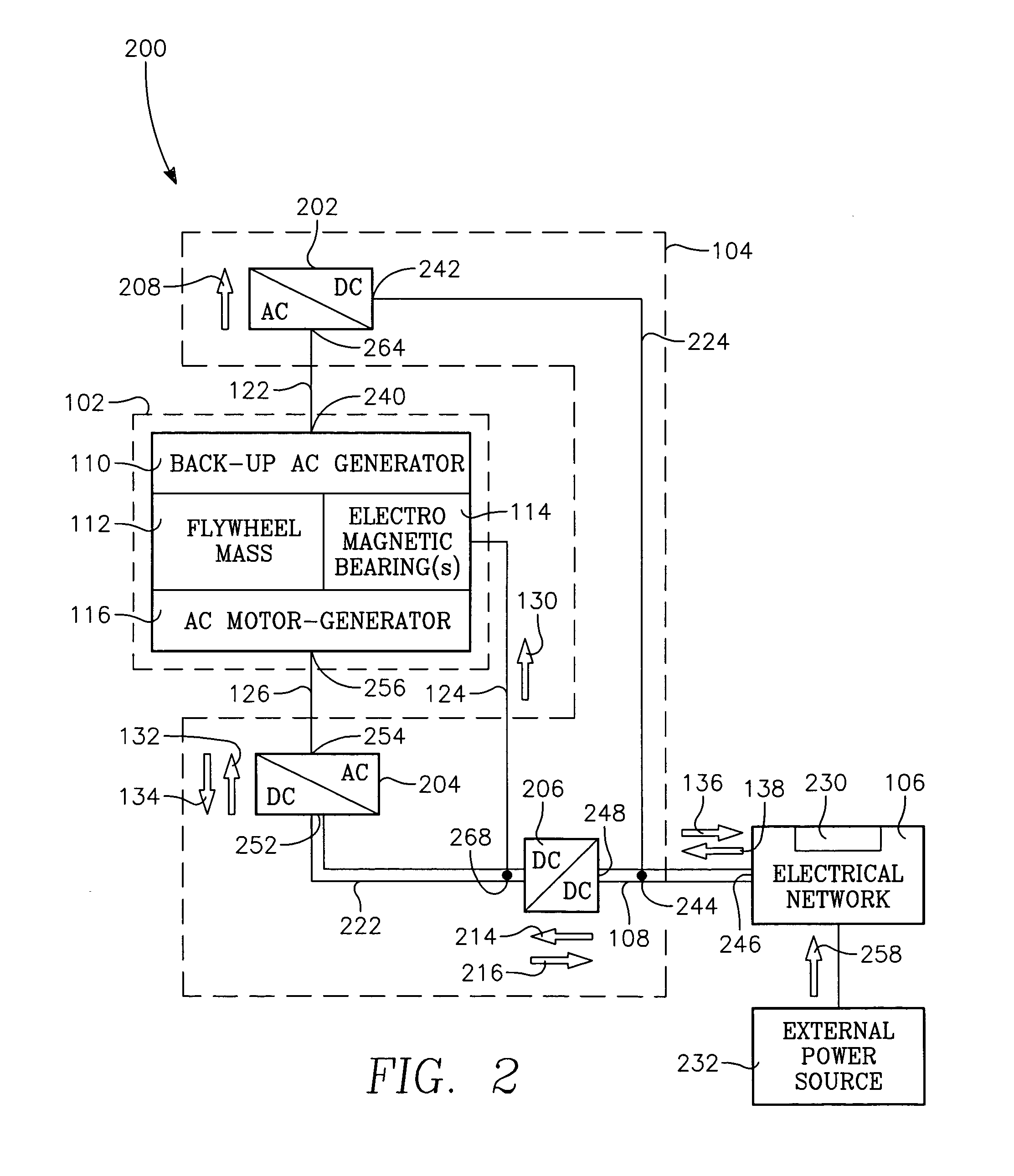
[0020]FIG. 2 shows the flywheel system including selected elements of the power electronics module 200. The power electronics module 104 includes three electric power converters. The first converter 202 is a uni-directional AC-to-DC converter, the second converter is a bi-directional AC-to-DC converter 204, and the third converter is a bi-directional DC-to-DC converter 206. The power electronics module also includes an internal DC bus 222, an external DC bus 108, and a fifth circuit 224.

[0021]As mentioned above, the first, second, and third circuits interconnect the power electronics module 104 and the flywheel module 102. What follows is a description of selected sources and users of electric power flowing in these circuits.

[0022]The first circuit 122 interconnects a backup generator AC output 240 as indicated by flow arrow 208 to a first converter AC input 264. The fifth circuit 224 connects a first converter DC output 242 to an external DC bus tap 244 on the external DC bus 108. ...

second embodiment

[0028]It should also be noted that while output 242 of first converter 202 may be processed by third converter 206 as shown in FIG. 2, in a second embodiment, a fourth unidirectional DC-to-DC electric power converter (not shown) might be used to interconnect first converter output 242 with the electromagnetic bearings 114. In this embodiment, the fourth converter adjusts the voltage level at first converter output 242 to accommodate the requirements of the electromagnetic bearings.

[0029]FIG. 3 shows selected flywheel module elements 300. Rotating elements include the flywheel shaft 346 and the flywheel mass 112. Stationery elements include the flywheel housing 358, first and second electromagnets 306, 318, and first and second electric stators 308, 342. The flywheel 360 includes the flywheel mass 112 and the flywheel shaft 346. The flywheel shaft includes first and second sections 310, 314. The flywheel shaft shares a common axis of rotation 322 with and is attached to the flywheel ...


PUM


Abstract

The present invention provides a flywheel system with a variable speed synchronous reluctance motor-generator and a variable speed permanent magnet generator for providing backup power. The flywheel system incorporates rotating elements supported by electromagnetic bearings. Electric power provided by the backup generator maintains electromagnetic bearing operation during that portion of the coast down period when shaft speed falls below the minimum required for operation of the synchronous reluctance motor-generator.

Description

[0001]This application claims priority from Provisional Application 60 / 476,226 filed Jun. 6, 2003.BACKGROUND OF THE INVENTION[0002]1. Field of the Invention[0003]The present invention relates to the electromechanical arts and energy storage systems. In particular, the present invention relates to flywheel systems used for energy storage and conversion.[0004]2. Description of Related Art[0005]Flywheel energy storage systems have provided a mechanical energy storage solution for hundreds of years as evidenced by the potter's wheel. Such systems differ in many respects from modern-day flywheel energy storage solutions. More recent design imperatives including high power density and electric power outputs have led to lightweight, high-speed flywheels operating in evacuated chambers and driving a similarly high-speed electric generator.[0006]A typical application for today's flywheel is to provide electric power to an electric network for a brief period of time, as might be needed when a...

Claims


Application Information

Patent Timeline
Patent Type & Authority Patents(United States)
IPC IPC(8): H02K7/09F16C39/06F16F15/315H02J9/06H02K7/02H02K7/18
CPCF16C32/0442F16C32/0457F16F15/315H02K7/025H02J9/066F16C2361/55H02K7/09H02K7/1807Y02E60/16F16C2380/28
Inventor KHALIZADEH, CLAUDE
Owner BEAVER AEROSPACE & DEFENSE
Why Eureka
Try Eureka