System for measuring signal path resistance for an integrated circuit tester interconnect structure

a technology of interconnect structure and signal path resistance, which is applied in the direction of resistance/reactance/impedence, measurement devices, instruments, etc., can solve problems such as failure of signal paths within the interconnect structure, failure of connection failure, and distortion of test results

Inactive Publication Date: 2006-09-19
FORMFACTOR INC
View PDF19 Cites 17 Cited by
  • Summary
  • Abstract
  • Description
  • Claims
  • Application Information

AI Technical Summary

Problems solved by technology

A connection failure may arise, for example, due to a contact misalignment, broken, missing or contaminated pins, probes or contact pads, open circuit or short circuit faults within interconnect structures or within test heads.
Interconnect structure assemblies are usually designed to provide signal paths having particular resistances, and variations from the intended resistance, due for example to corrosion or contamination on contact pads or the tips of probes, can distort test results.
However signal paths within an interconnect structure can fail after it leaves the factory when the structure is in use in an integrated circuit tester, and it is difficult and inconvenient to periodically remove an interconnect structure from a tester and manually test the continuity and resistance of its signal paths.
Open and short circuit signal path failures can often be detected, or at least suspected, when an interconnect structure is in use because such path failures normally lead to characteristic patterns of IC test failures.
However when a signal path has a resistance that is marginally outside an acceptable range, IC test failures may not exhibit a clear pattern.
Thus die can be improperly rejected as failing a test when the source of the failure was in fact the interconnect structure, and it may not be readily apparent that the failures are the fault of the interconnect structure, not the rejected die.

Method used


Image

  • System for measuring signal path resistance for an integrated circuit tester interconnect structure
  • System for measuring signal path resistance for an integrated circuit tester interconnect structure
  • System for measuring signal path resistance for an integrated circuit tester interconnect structure

Examples


Embodiment Construction

)

[0024]The present invention relates to a method and apparatus for measuring the resistance of signal paths through an interconnect structure providing signal paths between input / output (I / O) ports of a wafer level integrated circuit (IC) tester and test points on an IC wafer to be tested. Since the nature of the invention is best understood in the context of an IC tester architecture, a typical IC tester architecture is briefly outlined below.

Integrated Circuit Tester

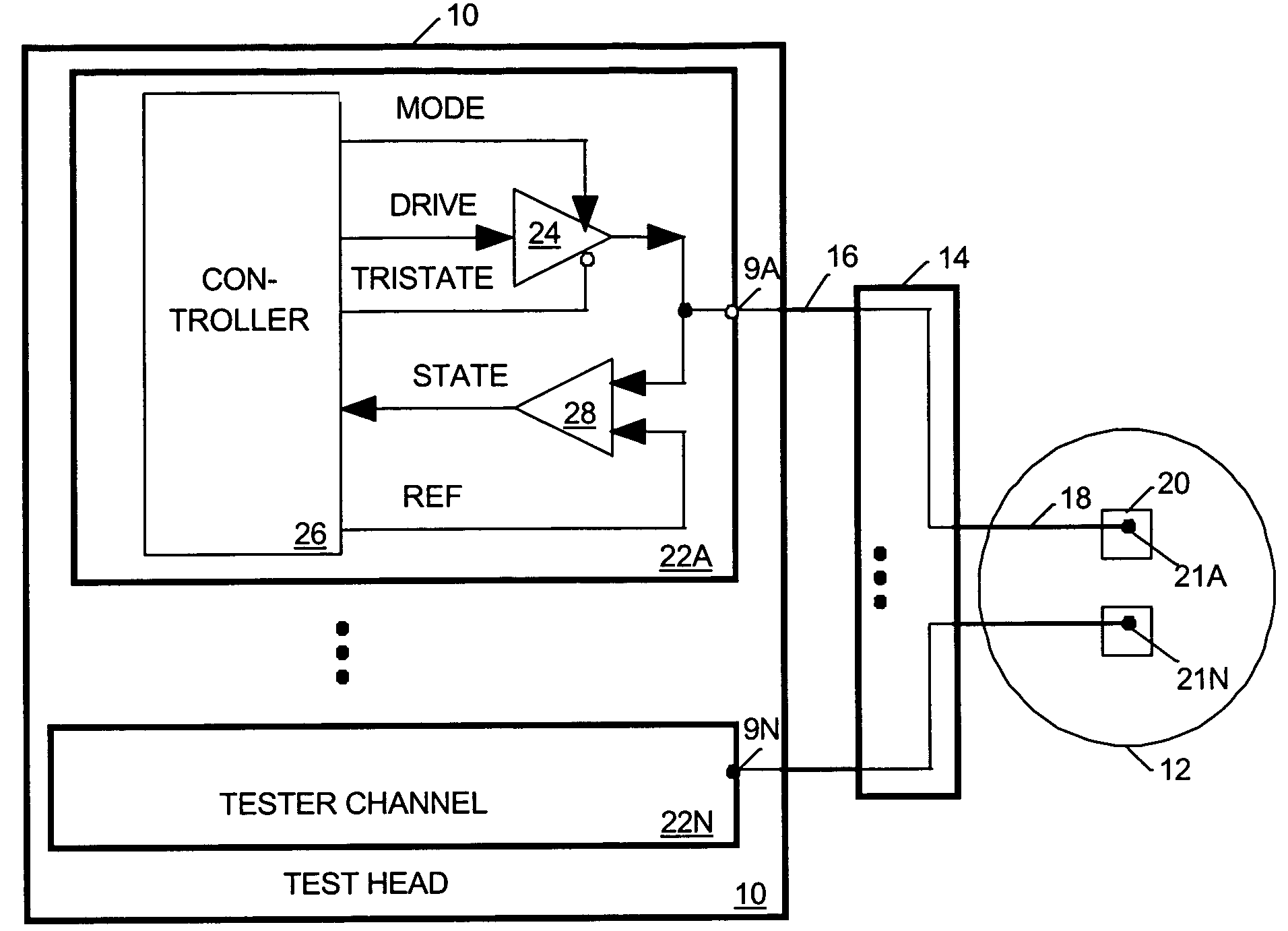
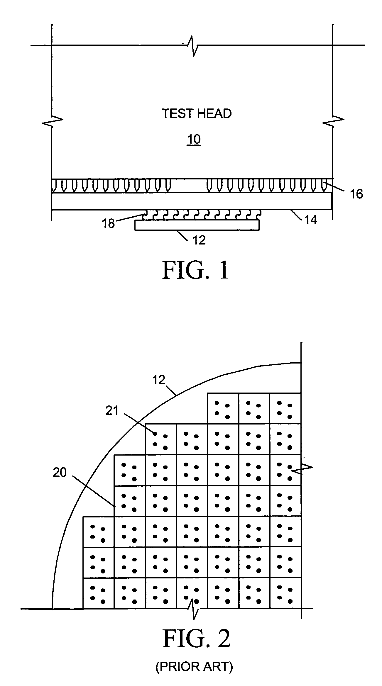
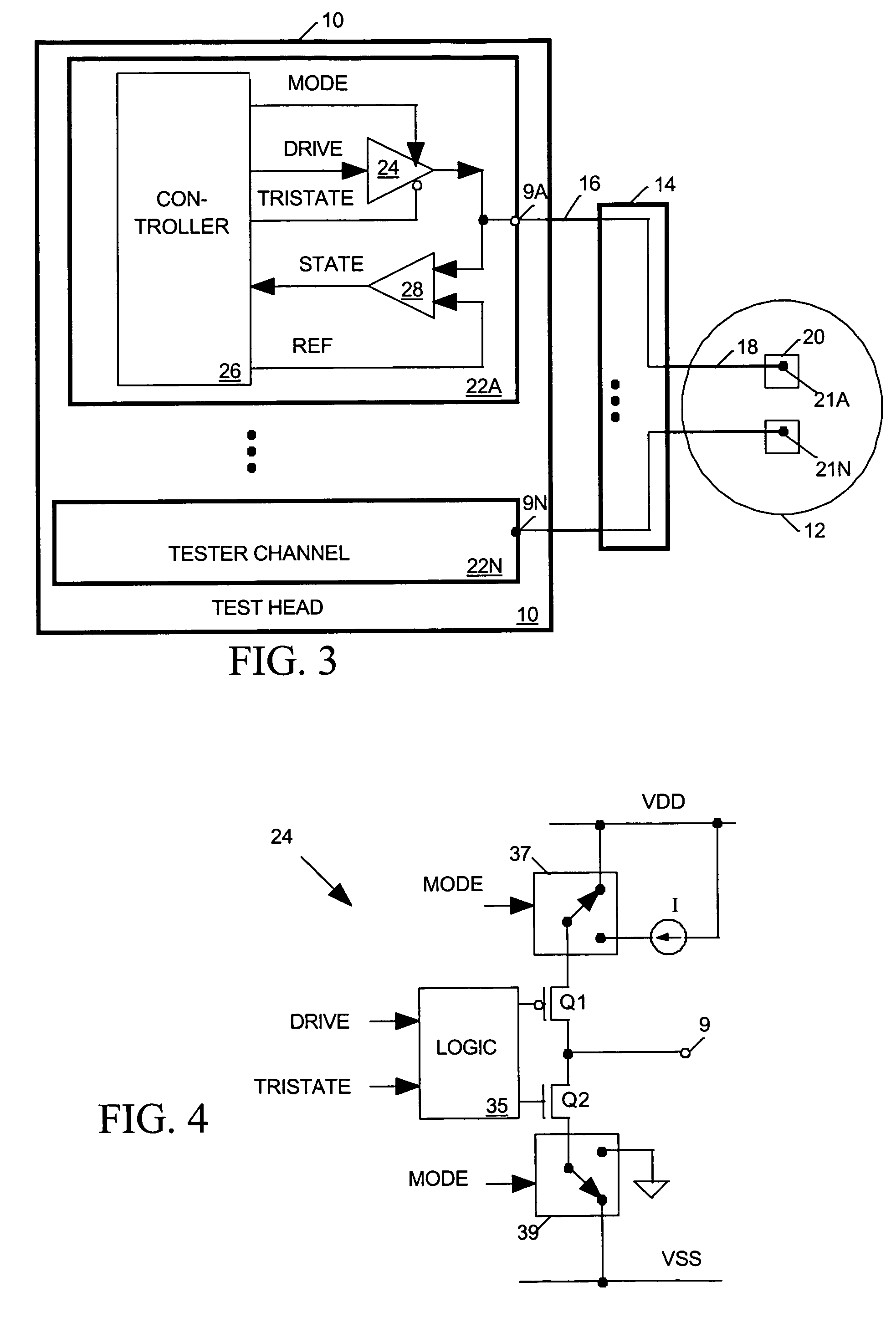
[0025]FIG. 1 is a simplified partial elevation view of a test head 10 of an IC tester accessing test points on a wafer under test 12 via a conventional interconnect structure 14. FIG. 2 is a simplified plan view of a portion of a wafer 12, and FIG. 3 is a simplified block diagram representing tester circuits that may be mounted in test head 10 of FIG. 1. Referring to FIGS. 1–3, test head 10 holds a set of circuit boards implementing circuits for carrying out both digital tests on ICs implemented in the form of die 20 o...


PUM


Abstract

Resistances of signal paths within a interconnect structure for linking input / output (I / O) ports of an integrated circuit (IC) tester to test points of an IC are measured by the IC tester itself. To do so the interconnect structure is used to link the tester's I / O ports to a similar arrangement of test points linked to one another through conductors. Drivers within the tester, which normally transmit digital test signals to IC test points via the I / O ports when the IC is under test, are modified so that they may also either transmit a constant current through the I / O ports or link the I / O ports to ground or other reference potential. The tester then transmits known currents though the signal paths interconnecting the tester's I / O ports. Existing comparators within the tester normally used to monitor the state of an IC's digital output signals are employed to measure voltage drops between the I / O ports, thereby to provide data from which resistance of signal paths within the interconnect structure may be computed.

Description

CROSS REFERENCE TO RELATED APPLICATION[0001]This application is DIV of Ser. No. 09 / 548,886 filed on Apr. 13, 2000, now U.S. Pat. No. 6,677,744.BACKGROUND OF THE INVENTION[0002]1. Field of the Invention[0003]The present invention relates in general to integrated circuit (IC) testers and in particular to a system for measuring the resistance of signal paths through an interconnect structure for linking an IC tester to test points on an IC to be tested.[0004]2. Description of Related Art[0005]It has become increasing popular to test integrated circuits while they are still in the form of die on a wafer. To do so, an IC tester must contact hundreds or thousands of test points on a wafer through an interconnect structure capable of providing a large number of signal paths between a tester's input / output (I / O) ports and test points on a wafer. Since the I / O ports of an IC tester are distributed over a much wider horizontal area than the test points they access, an interconnect structure l...

Claims


Application Information

Patent Timeline
Patent Type & Authority Patents(United States)
IPC IPC(8): G01R31/26G01R27/14G01R31/319G01R35/00
CPCG01R31/2853G01R35/00G01R31/31905G01R27/14G01R31/31924G01R31/31717
Inventor LONG, JOHN M.
Owner FORMFACTOR INC
Why Eureka
Try Eureka