Digital signal transmitter synchronization system

a digital signal and transmitter technology, applied in the field of digital signal transmitter synchronization systems, can solve the problems of insufficient measures, near completeness, internal interference in the system, etc., and achieve the effect of reducing the burden on adaptive equalizers

Active Publication Date: 2006-09-19
WEISS S MERRILL
View PDF20 Cites 72 Cited by
  • Summary
  • Abstract
  • Description
  • Claims
  • Application Information

AI Technical Summary

Benefits of technology

[0013]A primary objective of the present invention, therefore, is to provide a way to synchronize transmitters of digital signals to allow receivers, including television receivers, to treat signals received from multiple transmitters as a main signal and echoes. Once transmitters are synchronized, it becomes possible to adjust the timing of the signals emanating from those transmitters so as to minimize the burden placed on adaptive equalizers in receivers in areas with low system-internal C / I ratios.
[0016]By way of example, for the 8T-VSB system used for digital television transmission in the U.S., the Gaussian noise threshold (C / N ratio) of the system is approximately 15 dB. Adaptive equalizers in digital television receivers correct the reception of signals when echoes are in the range between 0 dB and 15–20 dB below the level of the received signal. (Older receiver designs operate only to within several dB below 0 dB. As of the time of this writing, new receiver designs are beginning to approach 0 dB. Future designs are expected to achieve 0-dB performance.) When the echoes are more than about 20 dB below the level of the received signal, they behave like noise to the receiver and are not corrected by the adaptive equalizer. The time range of echoes corrected by adaptive equalizers in current receiver designs can be up to 10 microseconds leading and 40 microseconds lagging the main signal. New designs are pushing those values to greater lengths of time, both leading and lagging. Longer time windows in receiver adaptive equalizers will make the design of single frequency networks more flexible.
[0017]In order to synchronize the transmitters and to permit the adjustment of their timing, a number of requirements must be met. To minimize the demands placed on adaptive equalizers, especially considering their short delay ranges and high amplitude differentiation requirements in some early receivers, it is necessary to time-adjust the signals from transmitters. The design objective is that the signals arrive in areas of low C / I ratios at times close enough to one another to fall within the adaptive equalizers' time windows.
[0018]Further, as explained above, it is necessary to have the transmitters emit identical signals for identical inputs. Because of various methods applied to improve system performance, many digital modulation schemes, including the 8T-VSB system, inherently produce random signals for given inputs, thereby stifling application of the system synchronization and timing principals discussed previously. A more particular object of the present invention, therefore, is to provide a method and apparatus to overcome the randomness of such modulation system outputs, including those of 8T-VSB systems, allowing synchronization without eliminating the advantages produced by the systems' features.

Problems solved by technology

Such measures are often inadequate, however, to avoid internal interference within the system.
When boosters are applied to analog signal coverage, including that of television signals, terrain blockage must be nearly complete since reception of signals from more than one transmitter will result in the appearance of echoes in the received signal, or ghosts in the received image.
A problem is that digital modulators often employ a number of processes that randomize the data that is fed to them.
In some such systems, there currently is no way to cause all such modulators to adopt the same states at the same time.
Such separated processing would not normally be possible because of the unsynchronized processes usually performed at the transmission location or locations.

Method used


Image

  • Digital signal transmitter synchronization system
  • Digital signal transmitter synchronization system
  • Digital signal transmitter synchronization system

Examples


Embodiment Construction

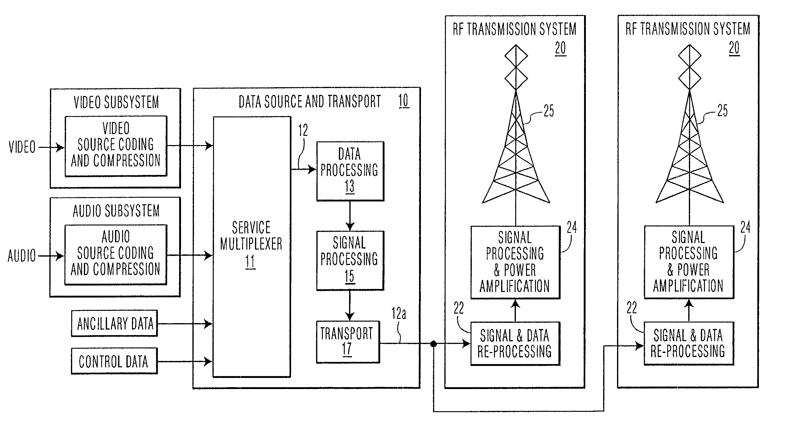
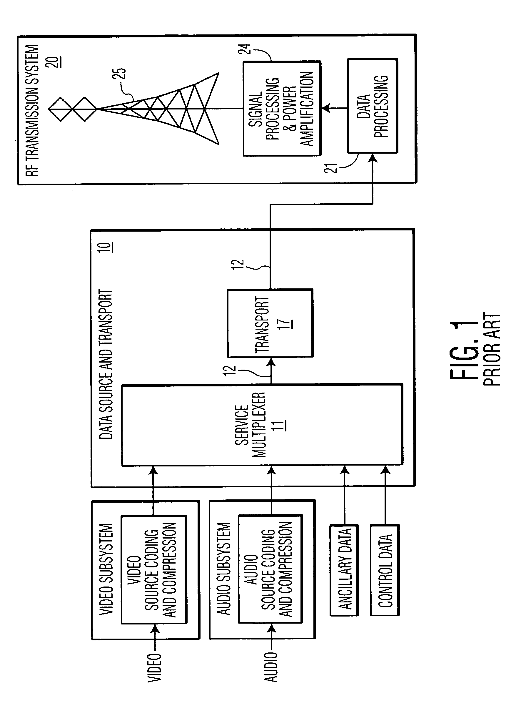
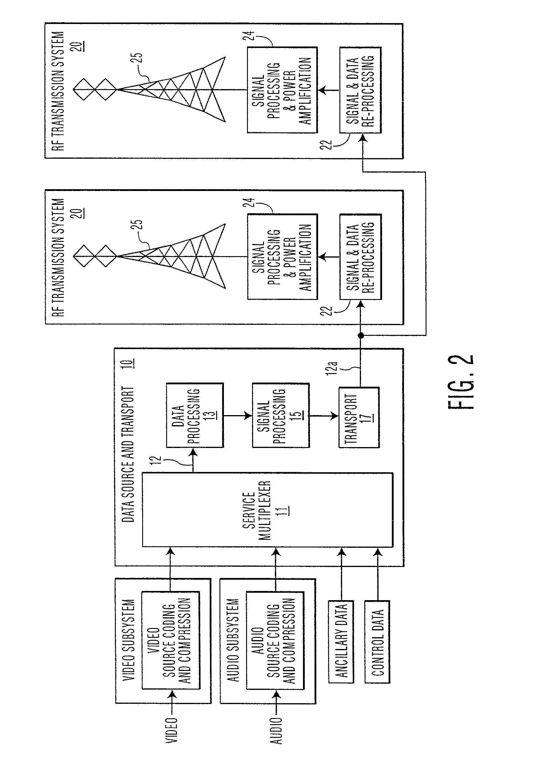
[0078]The preferred embodiments of the present invention will now be described with reference to FIGS. 1–21 of the drawings. Identical functional elements in the various figures are designated with the same reference numerals even though their precise operation may be different. The discussion to follow uses 8-VSB modulation of a digital television signal strictly for the sake of example. As will be recognized by those of ordinary skill in the art, the techniques described may be applied to a wide range of applications and types of modulation.

Overview of Synchronization Methods

[0079]The methods, systems and apparatus according to the present invention for synchronizing transmitters operate, in several embodiments, to insert reference signals into the data sent to the transmitters in order to place them into known states at specific times relative to the signals sent to them for transmission. In one embodiment, the methods, systems and apparatus according to the present invention ope...


PUM


Abstract

Methods, and apparatus for carrying out the methods, are disclosed for synchronizing a plurality of RF transmitters that are supplied with a common digital information signal for carrier modulation and subsequent transmission on a common channel throughout a prescribed region, whereby the digital signal receivers within the region may receive transmissions on the channel from more than one transmitter. The method involves inserting reference signals into the data sent to the transmitters in order to place them into known states at specific times relative to the digital signals sent to them for transmission. As a result of this method, the digital signals transmitted by each of the transmitters will be identical to one another so that the receivers will be able to identify one received signal as the main signal and the others as echoes. If necessary, the signal transmitted by at least one of the synchronized transmitters may be delayed, such that identical digital signals received from at least two of the transmitters by receivers in the region will arrive at each receiver within a prescribed time window. The methods and apparatus also can be applied to one or a plurality of RF transmitters for purposes of synchronizing processes at the source of the signals and at the transmitters.

Description

[0001]This Application claims the benefit of Provisional Application No. 60 / 280,364, filed Mar. 30, 2001.BACKGROUND OF THE INVENTION[0002]The present invention relates to methods, systems and apparatus for synchronizing digital signals, such as digital television (DTV) signals and other broadcast data signals, that are transmitted from a plurality of separated transmitting stations. It also allows the synchronization of the signal processing for transmission between a data source location and one or more transmitting locations.[0003]When television or other transmitted signals cannot reach certain locations because of terrain blockage or because interference considerations require a lower than desirable transmitted power in a given direction, it is possible to fill in the signal at such locations through the use of additional transmitters called “boosters” or “gap fillers.” This approach is well known in the art. It is also possible to extend coverage and to achieve more uniform sig...

Claims


Application Information

Patent Timeline
Patent Type & Authority Patents(United States)
IPC IPC(8): H04N7/12H04N5/38H04N21/2383H04N21/242H04N21/61
CPCH04N5/38H04N21/615H04N21/242H04N21/2383H04N7/015
Inventor WEISS, S. MERRILL
Owner WEISS S MERRILL
Why Eureka
Try Eureka