Determination of waveguide parameters

Active Publication Date: 2006-09-19
WESTERNGECO LLC
View PDF3 Cites 50 Cited by
  • Summary
  • Abstract
  • Description
  • Claims
  • Application Information

AI Technical Summary

Benefits of technology

[0007]The invention uses the multiple character of guided waves to obtain waveguide parameters, such as a wave propagation velocity within the waveguide (hereinafter referred to as a “waveguide velocity” for convenience”) and / or the thickness of a waveguide, from measurements of the wavefield recorded at the surface of the waveguide. If the waveguide thickness is of the order of the wavelength or thinner, the multiple reflections of the guided waves interfere with one another and so are not separable in the time domain. The invention overcomes this by making use of the fact that, in the frequency domain, the dispersion curves corresponding to different guided wave modes are separate. Parameters of the waveguide, such as waveguide velocity and the thickness of the waveguide may be determined from the dispersion curves in the frequency domain.

Problems solved by technology

If the waveguide thickness is of the order of the wavelength or thinner, the multiple reflections of the guided waves interfere with one another and so are not separable in the time domain.

Method used


Image

  • Determination of waveguide parameters
  • Determination of waveguide parameters
  • Determination of waveguide parameters

Examples


Embodiment Construction

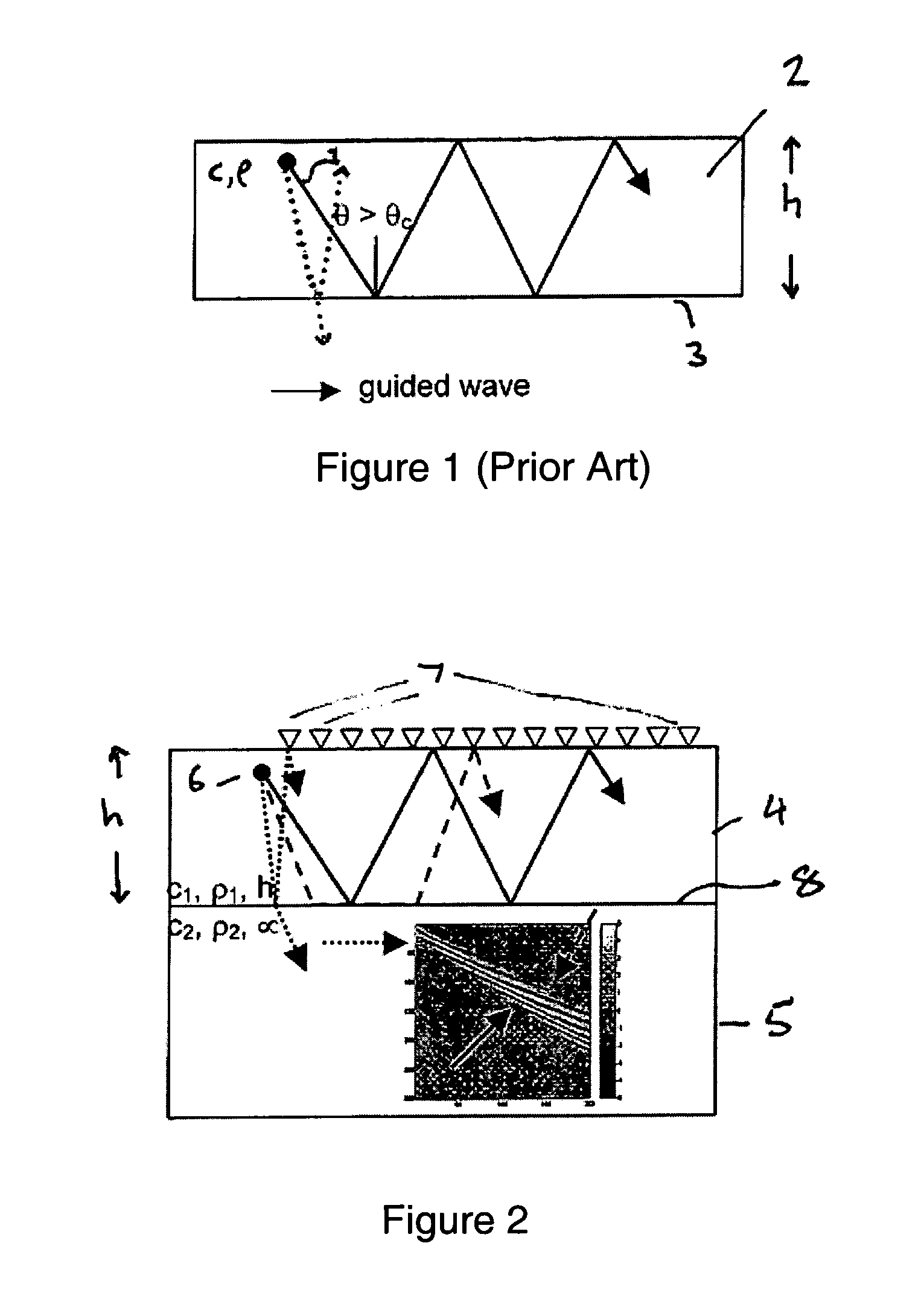
[0032]FIG. 2 illustrates typical paths of seismic energy at a survey location where the earth's interior is represented by a layer 5 that is overlaid by a thin layer 4. A seismic source 6 is located in the overlying layer 4 and, when actuated, emits seismic energy. The emitted seismic energy is detected by an array of suitable detectors 7 disposed at the earth's surface.

[0033]The overlying layer 4 has thickness h, acoustic velocity c1 and density ρ1. The underlying layer 5 has an acoustic velocity C2 and density ρ2, which are assumed to be different from the acoustic velocity and density of the overlying layer 4 (C2 will be greater than c1). In theory, the layer 5 is assumed to have infinite depth. However, in practice, described methods also work when layer 5 has finite depth.

[0034]FIG. 2 shows three possible paths of seismic energy emitted by the source 6. Seismic energy that travels along the path shown as a dotted line is incident on the interface 8 between the overlying layer 4...


PUM


Abstract

A method of determining at least one parameter of a waveguide (3) from wavefield data acquired from wave propagation in the waveguide including obtaining first and second dispersion curves (9a, 9b, 9c) in the frequency domain from the wavefield data. A frequency interval between the first dispersion curve and the second dispersion curve is found, and this is used in the determination of at least one parameter of the waveguide. The frequency separation Δƒ(V) between the first and second dispersion curves may be found at a particular value of the phase velocity V, and the thickness h of the waveguide can be found using:
Δf(V)=c12h1-c12V2
Here, c1 is the velocity of wave propagation in the waveguide. This may be found from the asymptotic velocity values of the dispersion curves.

Description

FIELD OF THE INVENTION[0001]The present invention relates to the determination of parameters of a waveguide from wavefield data acquired from waves propagating in the waveguide. The invention may be used to obtain information about, for example, the thickness of the waveguide and / or the velocity of propagation of waves within the waveguide.BACKGROUND OF THE INVENTION[0002]Guided waves result from multiple reflections in layered media. A guided wave occurs when a wave propagating in a layer is incident on a boundary of the layer at an angle to the surface normal greater than the “critical angle”. As is well known, when the incident angle to the surface normal is greater than the critical angle, the sine of the angle of transmission to the surface normal, as determined by Snell's Law, is greater than 1. A wave transmitted out of the layer may exist only as an evanescent wave, and the phenomenon of “total internal reflection” occurs. The waves are therefore trapped in the layer and pro...

Claims


Application Information

Patent Timeline
Patent Type & Authority Patents(United States)
IPC IPC(8): G01R23/16G01V1/30
CPCG01V1/30
Inventor ADLER, FRANKMUYZERT, EVERHARD
Owner WESTERNGECO LLC
Why Eureka
Try Eureka