Transmission line microwave apparatus including at least one non-reciprocal transmission line part between two parts

a technology of microwave apparatus and transmission line, which is applied in the direction of waveguides, electrical devices, antennas, etc., can solve the problems of increasing the scale of the apparatus according to the resonant, and no application to the antenna apparatus that employs the non-reciprocal left-handed transmission line circui

Active Publication Date: 2012-10-23
JAPAN SCI & TECH CORP
View PDF8 Cites 13 Cited by
  • Summary
  • Abstract
  • Description
  • Claims
  • Application Information

AI Technical Summary

Benefits of technology

[0020]The first object of the present invention is to solve the above problems and provide a transmission line microwave apparatus, such as a transmission line microwave circuit, a microwave resonator and a microwave circuit employing the same, which can be remarkably reduced in size in comparison with the prior art and has unique action and advantageous effects.
[0021]The second object of the present invention is to solve the above problems and provide a transmission line antenna apparatus, which forms a main beam by using a leaky wave from a transmission line such as a left-handed or right-handed transmission line and is able to control the main beam direction.Means for Dissolving the Problems
[0022]According to the first aspect of the present invention, there is provided a transmission line microwave apparatus including at least one nonreciprocal transmission line part, where the nonreciprocal transmission line part has a series branch circuit equivalently including a capacitive element and a shunt branch circuit equivalently including an inductive element, and the nonreciprocal transmission line part has gyrotropic characteristics by being magnetized in a magnetization direction different from a propagation direction of a microwave. In this case, the nonreciprocal transmission line part has an asymmetric structure with respect to a plane formed by the propagation direction and the magnetization direction, and the nonreciprocal transmission line part has a predetermined propagation constant and an operating frequency set in a dispersion curve that represents a relation between the propagation constant and the operating frequency so that a propagation constant in a forward direction and a propagation constant in a backward direction have nonreciprocal phase characteristics different from each other. The transmission-line microwave apparatus includes a microwave transmission line constituted by cascade-connecting the at least one nonreciprocal transmission line part between first and second ports.
[0023]In the above-mentioned transmission line microwave apparatus, the predetermined propagation constant and the operating frequency are set in the dispersion curve so that the power transmission is performed by left-handed transmission in a direction from the first port toward the second port and the power transmission is performed by right-handed transmission in a direction from the second port toward the first port in the microwave transmission line at a predetermined operating frequency.
[0024]In addition, in the above-mentioned transmission line microwave apparatus, the predetermined propagation constant and the operating frequency are set in the dispersion curve so that electric power transmission is performed by left-handed transmission or right-handed transmission in a direction from the first port toward the second port and the power transmission is performed so that the propagation constant is zero and a guide wavelength is infinite in a direction from the second port to the first port in the microwave transmission line at the predetermined operating frequency.
[0025]Further, in the above-mentioned transmission line microwave apparatus, the microwave transmission line is a microwave phase shifter that is constituted by setting the predetermined propagation constant and the operating frequency in the dispersion curve to shift the phase by a predetermined amount of phase shift.

Problems solved by technology

However, no application to the antenna apparatus that employs the nonreciprocal left-handed transmission line circuit has been reported.
In particular, a resonant frequency in conventional microwave resonators is determined depending on the line length, and the microwave circuit employing the resonators, and the resonators themselves therefore have led to a problem that the apparatus configuration is increased in scale depending on the resonant frequency.

Method used


Image

  • Transmission line microwave apparatus including at least one non-reciprocal transmission line part between two parts
  • Transmission line microwave apparatus including at least one non-reciprocal transmission line part between two parts
  • Transmission line microwave apparatus including at least one non-reciprocal transmission line part between two parts

Examples


eleventh and twelfth

[0318 Preferred Embodiments

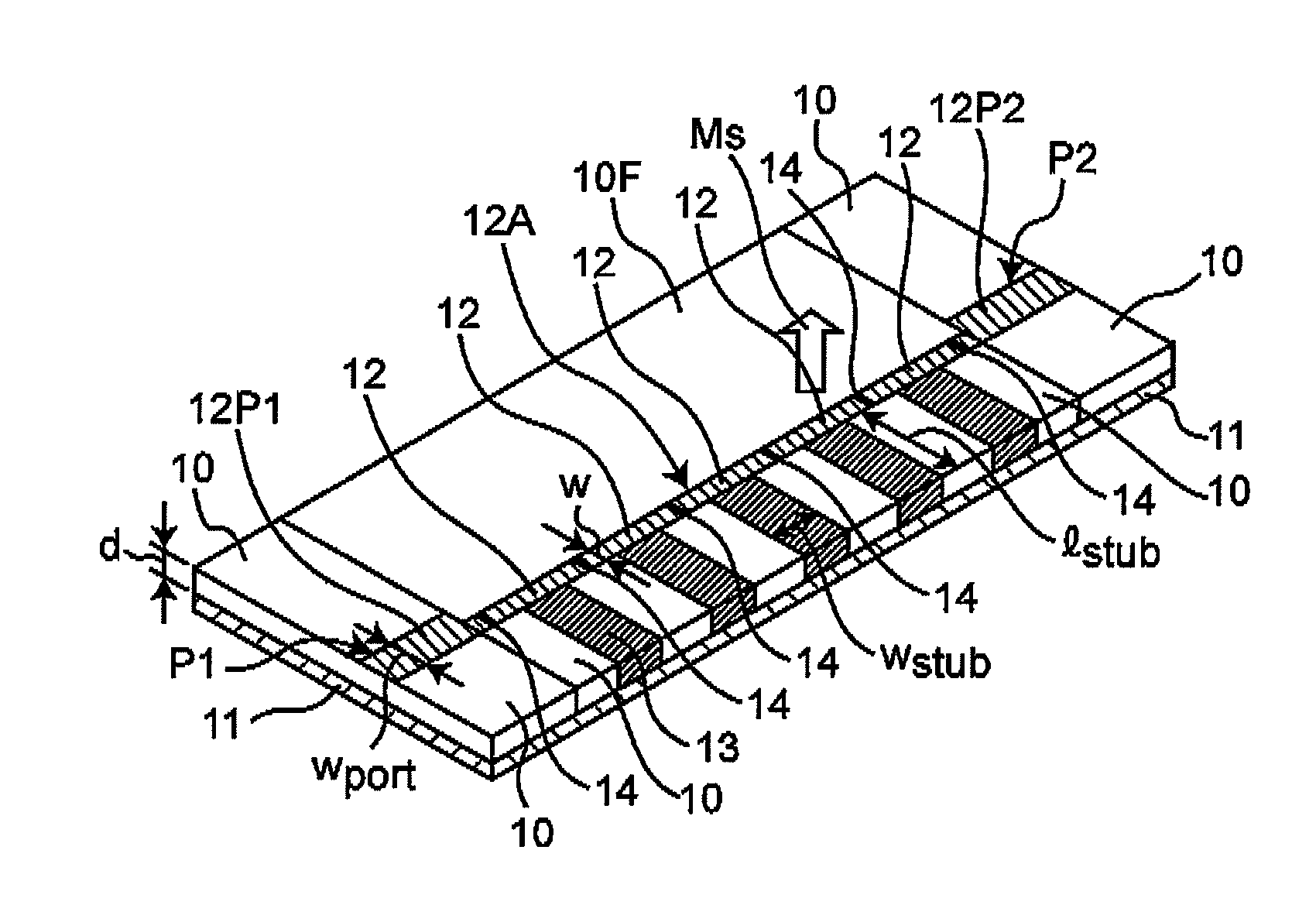
[0319]FIG. 35 is a perspective view showing the external appearance of a band-stop filter that employs the ladder type nonreciprocal right / left handed transmission line of the first preferred embodiment according to an eleventh preferred embodiment of the present invention. FIG. 36 is a block diagram showing a configuration of a band-pass filter that employs the ladder type nonreciprocal right / left handed transmission line of the first preferred embodiment according to a twelfth preferred embodiment of the present invention.

[0320]By coupling at least one or more nonreciprocal resonators and a power feeding transmission line at an edge or a side as a filter that employs the nonreciprocal transmission line type resonator of the present preferred embodiment as in the prior art filter that employs the transmission line type resonator, the following filters can be constituted:

[0321](i) A filter including a transmission line type resonator that employs a nonreci...


PUM


Abstract

A transmission line microwave apparatus includes at least one nonreciprocal transmission line part, which includes a series branch circuit equivalently including a capacitive element and a shunt branch circuit equivalently including an inductive element. The nonreciprocal transmission line part has gyrotropic characteristic by being magnetized in a magnetization direction different from the propagation direction of a microwave, and has an asymmetric structure to a plane formed by the propagation direction and the magnetization direction. The nonreciprocal transmission line part has a propagation constant and an operating frequency set in a dispersion curve that represents a relation between the propagation constant and the operating frequency so that the propagation constant in the forward direction and the propagation constant in the backward direction have nonreciprocal phase characteristics different from each other. A microwave transmission line is constituted by cascade-connecting at least one non-reciprocal transmission line part between first and second ports.

Description

TECHNICAL FIELD[0001]The present invention relates to a transmission-line microwave apparatus provided with a transmission-line microwave circuit employing a nonreciprocal transmission line that has a nonreciprocal phase characteristic such that a propagation constant in a forward direction and a propagation constant in a backward direction are different from each other, and to a novel transmission-line antenna apparatus that uses a leaky wave from the nonreciprocal transmission line. It is noted that the microwave in the present specification refers to, for example, microwave, millimeter wave, sub-millimeter wave and terahertz wave in a frequency band higher than the UHF (Ultra High Frequency) band. A“nonreciprocal right-handed and left-handed transmission line” is hereinafter referred to as a “nonreciprocal right / left handed transmission line”.BACKGROUND ART[0002]Recently, researches on the left-handed transmission (Left Handed Transmission (LHT)) line in which the inductance and ...

Claims


Application Information

Patent Timeline
Patent Type & Authority Patents(United States)
IPC IPC(8): H01P3/08
CPCH01P1/203H01P1/207H01P1/32H01Q1/38H01Q13/206
Inventor UEDA, TETSUYA
Owner JAPAN SCI & TECH CORP
Why Eureka
Try Eureka