
Water monitoring systems

a water monitoring and water supply technology, applied in the field of water monitoring systems, can solve the problems of significant health risks, contaminated drinking water supplies for domestic civilian consumption, and those for deployed military forces, and is susceptible to being contaminated with potentially toxic chemicals

Inactive Publication Date: 2006-09-19
BAE SYSTEMS LAND & ARMAMENTS LP
View PDF6 Cites 25 Cited by
  • Summary
  • Abstract
  • Description
  • Claims
  • Application Information

AI Technical Summary

Benefits of technology

"The invention is a water supply monitoring system that includes a test unit, a plumbing system, a fluorometer, and a control module. The system can communicate fluorescence induction data to a remotely located control system using a data link. The control system can display the data on a control and display panel. The technical effect of this invention is to provide a convenient and efficient way to monitor water supply quality and stability."

Problems solved by technology

Supplies of drinking water for domestic civilian consumption, as well as those for deployed military forces, are vulnerable to being contaminated with potentially toxic chemicals, such as nerve agents, blood agents, and concentrations of herbicides and / or pesticides.
All of these chemicals when present in sufficient amounts can be detrimental to the health of anyone who drinks the contaminated water.
In addition, algae can survive on low concentrations of nutrients and / or on nutrients that are in forms unsuitable for large multi-cellular organisms.
Additionally, it is also known that a change in the fluorescence induction spectrum or pattern of a plant can represent a change in photosynthetic capability, which can be caused by the presence of toxic chemicals.
Additionally, with the large quantity of pesticides and herbicides employed by modern society, it is possible that an unknown, accidental leak of a toxin could occur that could pose significant health risks.
The large number of water sources, along with the relative size of the water sources, also makes continuous human monitoring and testing of surface water sources a cumbersome, expensive and potentially impossible task.

Method used


Image

  • Water monitoring systems
  • Water monitoring systems
  • Water monitoring systems

Examples


Embodiment Construction

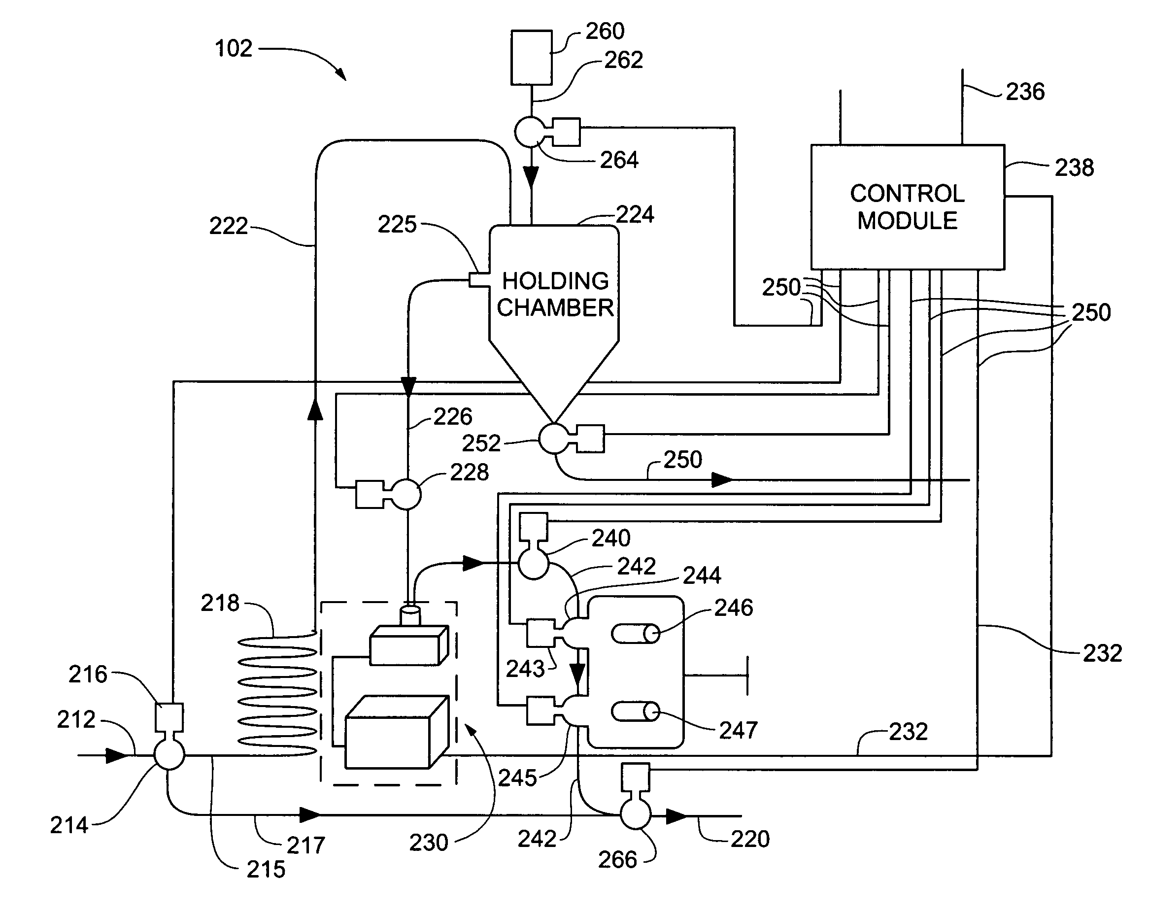
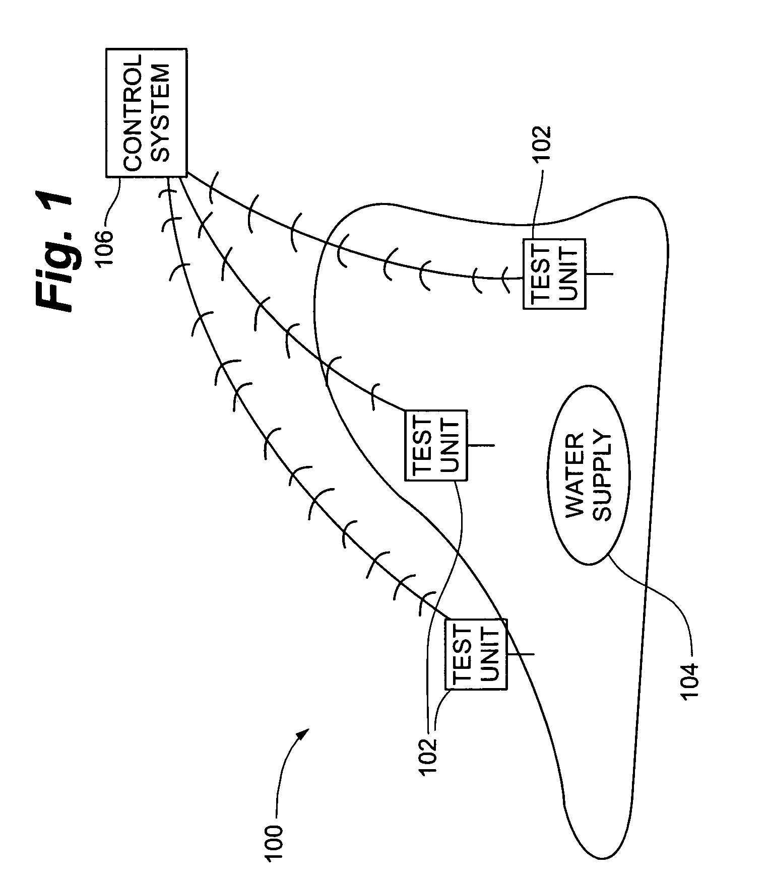
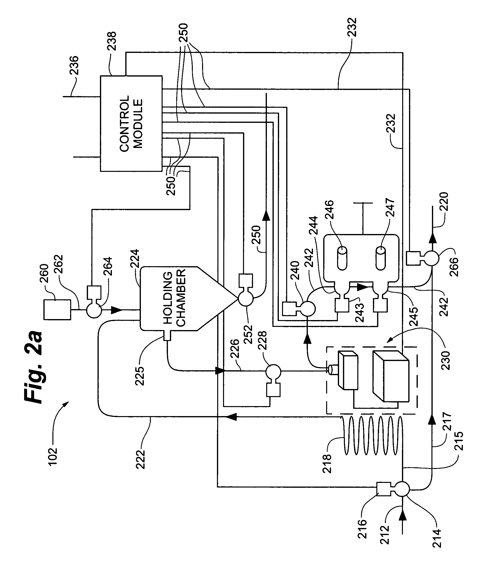
[0016]Improved water monitoring systems comprise a test unit having an analytical device and a control system in communication with the test unit such that water supply data generated at the test unit can be communicated to the control system. In some embodiments, the analytical device can be a fluorometer that can monitor the fluorescence induction pattern of algae located in the water, which can indicate, when the induction pattern is compared against known baseline induction patterns, the potential presence of toxic chemicals located in the water supply. In other embodiments, the analytical device can comprise, for example, a pH meter, an infrared spectroscopy (IR) device or the like. In some embodiments, the test unit can provide continuous intake, analysis, and can communicate water supply data to the control system via a wireless communication device, fiber optical cable or the like. In some embodiments, a plurality of test units can be in communication with a single remotely ...


PUM


Abstract

Improved water monitoring systems comprise a test unit having an analytical device and a control system in communication with the test unit such that water supply data generated at the test unit can be communicated to the control system. In some embodiments, the analytical device can be a fluorometer that can monitor the fluorescence induction pattern of algae located in the water, which can indicate, when the induction pattern is compared against known baseline induction patterns, the potential presence of toxic chemicals located in the water supply. In other embodiments, the analytical device can comprise, for example, a pH meter, an infrared spectroscopy (IR) device or the like. In some embodiments, the test unit can provide continuous intake, analysis, and can communicate water supply data to the control system via a wireless communication device, fiber optic cable or the like.

Description

CROSS-REFERENCE TO RELATED APPLICATIONS[0001]The current application claims the benefit of priority from U.S. Provisional Patent Application filed on Jul. 24, 2003, entitled “Water Supply Monitoring Device and Method” having Ser. No. 60 / 490,062, which is hereby incorporated by reference herein.FILED OF THE INVENTION[0002]The present invention relates to devices and methods for monitoring a supply of drinking water, and more particularly, to such devices and methods that can remotely monitor the presence of toxic agents in one or more water supplies.BACKGROUND OF THE INVENTION[0003]Supplies of drinking water for domestic civilian consumption, as well as those for deployed military forces, are vulnerable to being contaminated with potentially toxic chemicals, such as nerve agents, blood agents, and concentrations of herbicides and / or pesticides. All of these chemicals when present in sufficient amounts can be detrimental to the health of anyone who drinks the contaminated water. In or...

Claims


Application Information

Patent Timeline
Patent Type & Authority Patents(United States)
IPC IPC(8): G06F15/00G06F11/00
CPCG01N21/85G01N21/6486C02F2209/008C02F2209/06G01N2021/635
Inventor MCCARTER, STEVEN M.JENKINS, RONALD W.
Owner BAE SYSTEMS LAND & ARMAMENTS LP
Learn More