Fixed blade fixed cutter hole opener

a fixed cutter and cutter technology, applied in the direction of cutting machines, shaft sinking, shaft equipment, etc., can solve the problems of increasing the diameter of the wellbore, increasing the tendency to “torque-up”, and difficulty in directionally drilling a wellbore with a large diameter bit. achieve the effect of increasing the diameter

Inactive Publication Date: 2006-09-26
SMITH INT INC
View PDF8 Cites 48 Cited by
  • Summary
  • Abstract
  • Description
  • Claims
  • Application Information

AI Technical Summary

Benefits of technology

[0015]In another aspect, the invention is a hole opener including a tool body having upper and lower ends adapted to be coupled to adjacent drilling tools. At least two blades are formed on the tool body and are arranged so that the hole opener is positioned substantially concentric with a wellbore when disposed therein. A plurality of cutting elements are disposed on the at least two blades. The at least two blades and the plurality of cutting elements are adapted to increase a diameter of a previously drilled wellbore. The plurality of cutting elements are arranged so as to substantially balance work performed by each of the at least two blades.

Problems solved by technology

Further, increasing the diameter of the wellbore may be necessary if, for example, the formation being drilled is unstable such that the wellbore diameter changes after being drilled by the drill bit.
It is difficult to directionally drill a wellbore with a large diameter bit because, for example, larger diameter bits have an increased tendency to “torque-up” (or stick) in the wellbore.
This arrangement, among other factors, forms a relatively unreliable mechanical structure that is not durable, especially when drilling tough formations.
Moreover, some prior art hole openers generate high levels of vibration and noise, and tend to cause the well trajectory deviate from the existing well trajectory.

Method used


Image

  • Fixed blade fixed cutter hole opener
  • Fixed blade fixed cutter hole opener
  • Fixed blade fixed cutter hole opener

Examples


Embodiment Construction

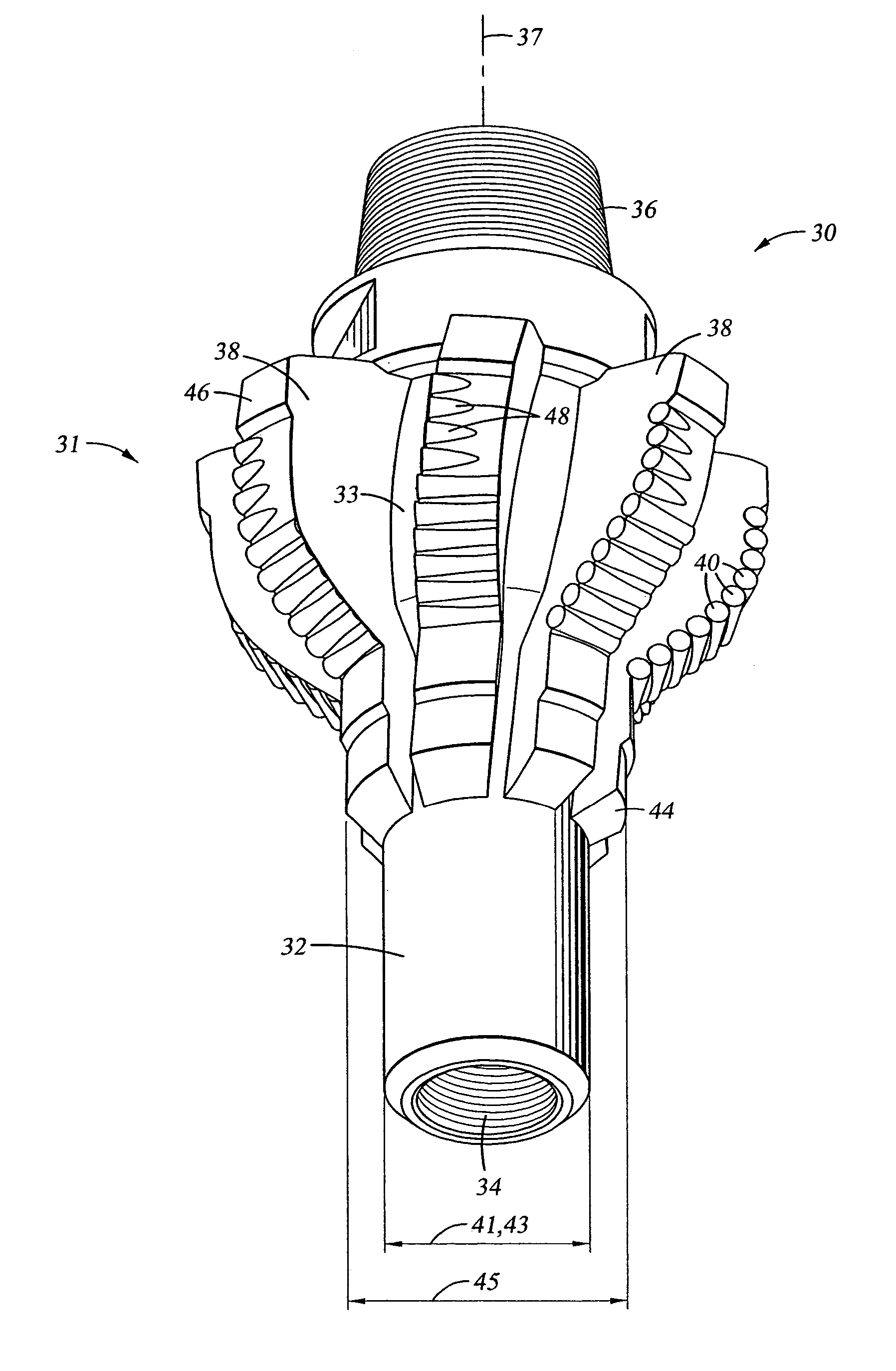
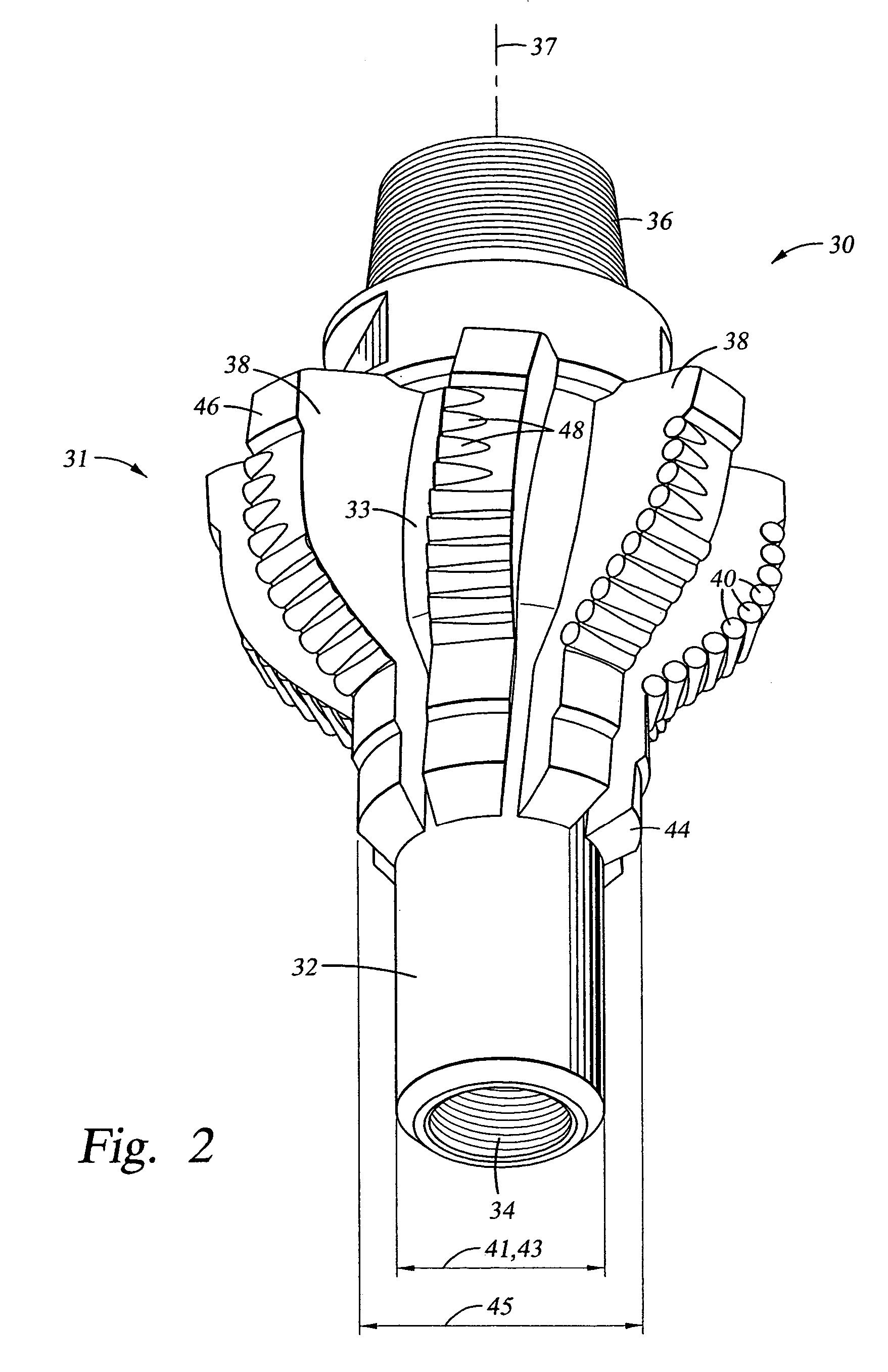
[0034]FIG. 2 shows a general configuration of a hole opener 30 that includes one or more aspects of the present invention. The hole opener 30 includes a tool body 32 and a plurality of blades 38 disposed at selected azimuthal locations about a circumference thereof. The hole opener 30 generally comprises connections 34, 36 (e.g., threaded connections) so that the hole opener 30 may be coupled to adjacent drilling tools that comprise, for example, a drillstring and / or bottom hole assembly (BHA) (not shown). The tool body 32 generally includes a bore (35 in FIG. 4) therethrough so that drilling fluid may flow through the hole opener 30 as it is pumped from the surface (e.g., from surface mud pumps (not shown)) to a bottom of the wellbore (not shown). The tool body 32 may be formed from steel or from other materials known in the art. For example, the tool body 32 may also be formed from a matrix material infiltrated with a binder alloy.

[0035]The blades 38 shown in FIG. 2 are spiral bla...


PUM


Abstract

A hole opener including a tool body having upper and lower ends. The upper and lower ends may be coupled to adjacent drilling tools. At least two blades are formed on the tool body and are arranged so that the hole opener is positioned concentric with a wellbore, and cutting elements are located on the blades. The at least two blades and the cutting elements are arranged to increase a diameter of a previously drilled wellbore.
A hole opener including a tool body having upper and lower ends. The upper and lower ends may be coupled to adjacent drilling tools. At least two blades are formed on the tool body and are arranged so that the hole opener is positioned concentric with a wellbore, and cutting elements are located on the blades. The hole opener includes a pilot hole conditioning section. The pilot hole conditioning section includes at least two pilot blades formed on the tool body in a position axially ahead of the blades. The pilot blades include a taper at a downhole end and gage pads positioned at selected diameters. At least one cutting element is disposed on the pilot blades.

Description

CROSS-REFERENCE TO RELATED APPLICATIONS[0001]This application is a continuation of U.S. patent application Ser. No. 10 / 156,727, filed on May 28, 2002, now U.S. Pat. No. 6,742,607 and claims the benefit, pursuant to 35 U.S.C. §120, of that application. That application is incorporated by reference in its entirety.BACKGROUND OF INVENTION[0002]1. Field of the Invention[0003]The invention relates generally to downhole tools used to enlarge wellbores drilled in earth formations. More specifically, the invention relates to a fixed blade fixed cutter hole opener having an advanced cutting structure and gage configuration.[0004]2. Background Art[0005]Polycrystalline diamond compact (PDC) cutters have been used in industrial applications including wellbore drilling and metal machining for many years. In these applications, a compact of polycrystalline diamond (or other superhard material such as cubic boron nitride) is bonded to a substrate material, which is typically a sintered metal-carbi...

Claims


Application Information

Patent Timeline
Patent Type & Authority Patents(United States)
IPC IPC(8): E21B7/28E21B10/26E21B10/42E21B10/43
CPCE21B10/43E21B10/26
Inventor BEATON, TIMOTHY P.
Owner SMITH INT INC
Why Eureka
Try Eureka