Combined temperature and pressure probe for a gas turbine engine

Inactive Publication Date: 2006-09-26
SWONGER JR KARL WILLIAM
View PDF33 Cites 42 Cited by
  • Summary
  • Abstract
  • Description
  • Claims
  • Application Information

AI Technical Summary

Problems solved by technology

The wiring harness, electrical connector and pressure tube add wei

Method used


Image

  • Combined temperature and pressure probe for a gas turbine engine
  • Combined temperature and pressure probe for a gas turbine engine
  • Combined temperature and pressure probe for a gas turbine engine

Examples


Embodiment Construction

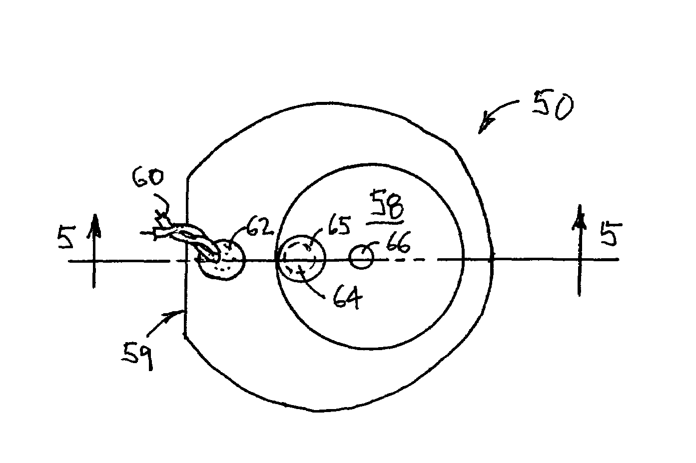
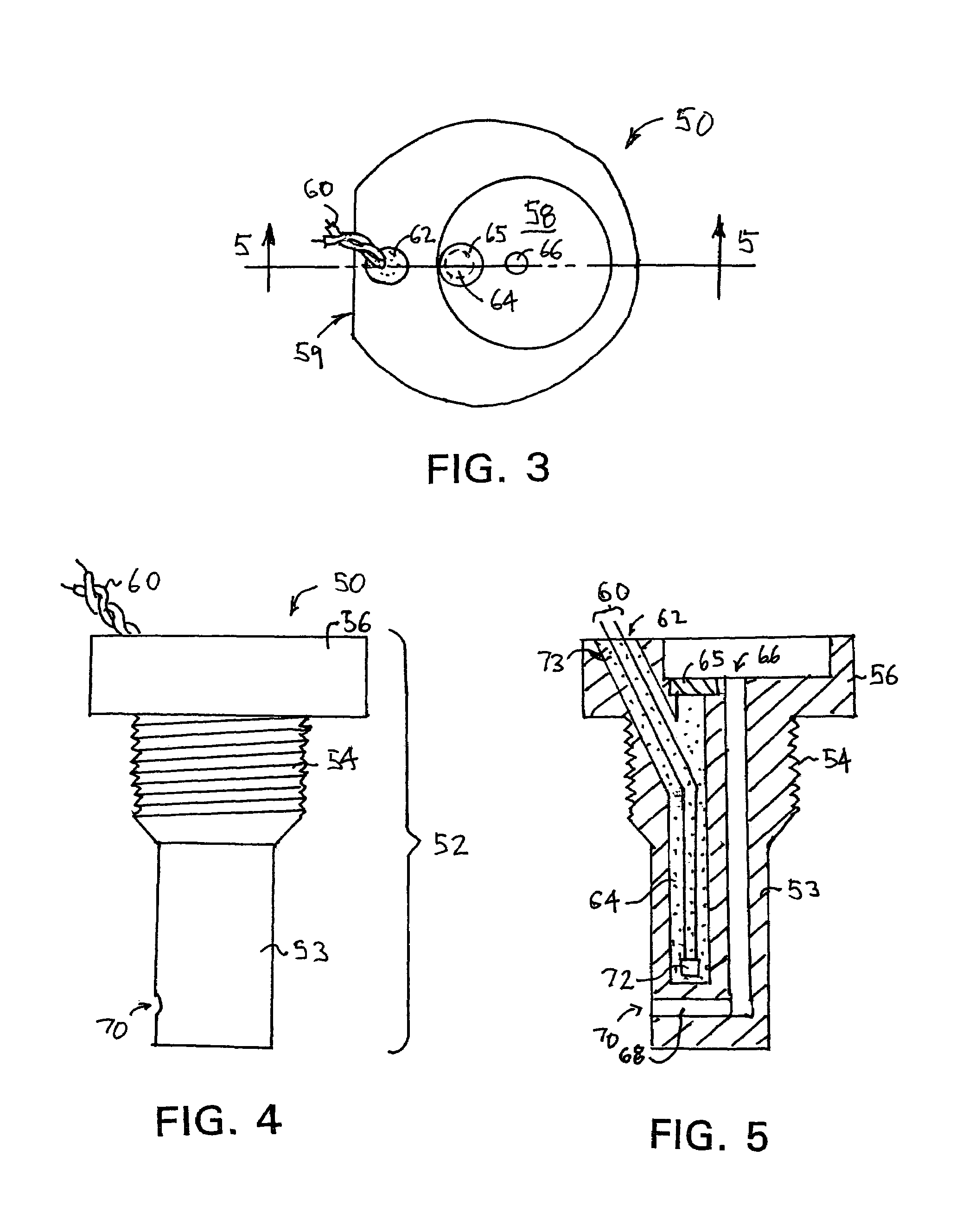
[0027]Referring again to the drawings, there is illustrated in FIGS. 3 and 4 a combined temperature and pressure probe 50 that is in accordance with the present invention. The probe 50 has a stepped cylindrical body that is formed from a durable metal such as aluminum, or an alloy such as brass, that has a high coefficient of heat conductivity. As best seen in FIG. 4, the probe body 52 has three stepped portions having different diameters. A lower portion 53 has the smallest diameter and extends into the air stream being sampled. A middle portion 54 has a diameter that is greater than the diameter of the lower portion 52 and is threaded to receive a securing nut, as will be explained below. An upper portion 56 has a diameter that is greater than the diameter of the middle portion 54. As will also be explained below, the probe upper portion 56 is contained within an engine control housing. A circular recess 58 is formed in the top surface of the probe upper portion 56. Additionally, ...


PUM


Abstract

A probe that includes both a temperature transducer and a pressure sensing port is adapted to be mounted upon and extend into the intake housing of a gas turbine engine. The probe is operative to provide air temperature and pressure data to an engine controller for the gas turbine engine.

Description

BACKGROUND OF THE INVENTION[0001]This invention relates in general to gas turbine engines and in particular to a combined temperature and pressure probe for intake air to a gas turbine engine.[0002]Gas turbine engines, or jet engines, have been widely adopted to power aircraft, where their simplicity and operating efficiency provides high reliability with low operating costs. A sectional view of a gas turbine engine is shown generally at 10 in FIG. 1. The engine 10 includes three primary parts. A compressor 12 located to the left of FIG. 1 is disposed within an engine intake housing 13. The compressor 12 consists of a plurality of fan blades 14 attached in rows to a cone-shaped cylinder 16. To the right of the compressor 12 is the second primary part of the engine, which is a combustion chamber 18. The combustion chamber 18 includes a perforated flame holder 20 that has a generally cylindrical shape. A plurality of fuel injectors are 22 positioned at the left end of the flame holder...

Claims


Application Information

Patent Timeline
IPC IPC(8): G01K1/14G01K7/02
CPCG01K13/02G01K13/028G01K2205/02
Inventor SWONGER, JR., KARL WILLIAM
Owner SWONGER JR KARL WILLIAM
Why Eureka
Try Eureka