Blades

Active Publication Date: 2006-09-26
ROLLS ROYCE PLC
View PDF9 Cites 34 Cited by
  • Summary
  • Abstract
  • Description
  • Claims
  • Application Information

AI Technical Summary

Benefits of technology

[0011]Typically, the rupturable elements comprise capsules or other elements embedded within the matrix. Generally, these rupturable elements are uni-operational or reactive. Typically, uni-operational rupturable elements upon rupture provide their own outward pressure in co-operation with other rupturable elements. Generally, reactive rupturable elements release upon rupture reactants in order to react with other reactants from other reactive rupturable elements in order to provide the outward pressure. Alternatively, reactive rupturable elements react with the matrix in order to provide the outward pressure. Typically, the r

Problems solved by technology

However, it will also be understood that in view of the significant air flow rates there is a high danger with regard to impacts, particularly upon the fan blades of the propulsive fan 12 at the air intake 11 end of the engine 10.
In such circumstances, the inherent reduced weakness and susceptibility to deformation of hollow fan blades is a significant problem.
Nevertheless, it will be appreciated that these hollow cavity fillings being of an elastomeric nature will still become distorted with the fan blade when exposed to sev

Method used


Image

  • Blades
  • Blades
  • Blades

Examples


Embodiment Construction

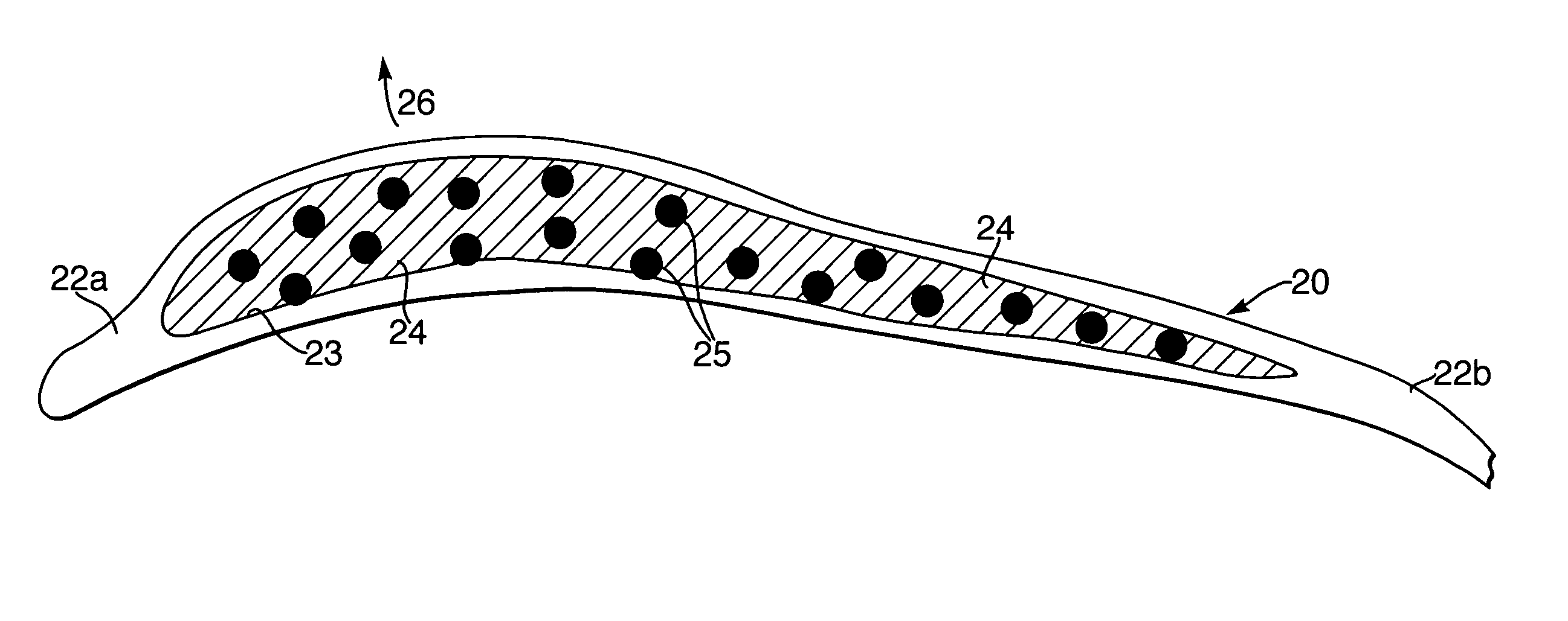
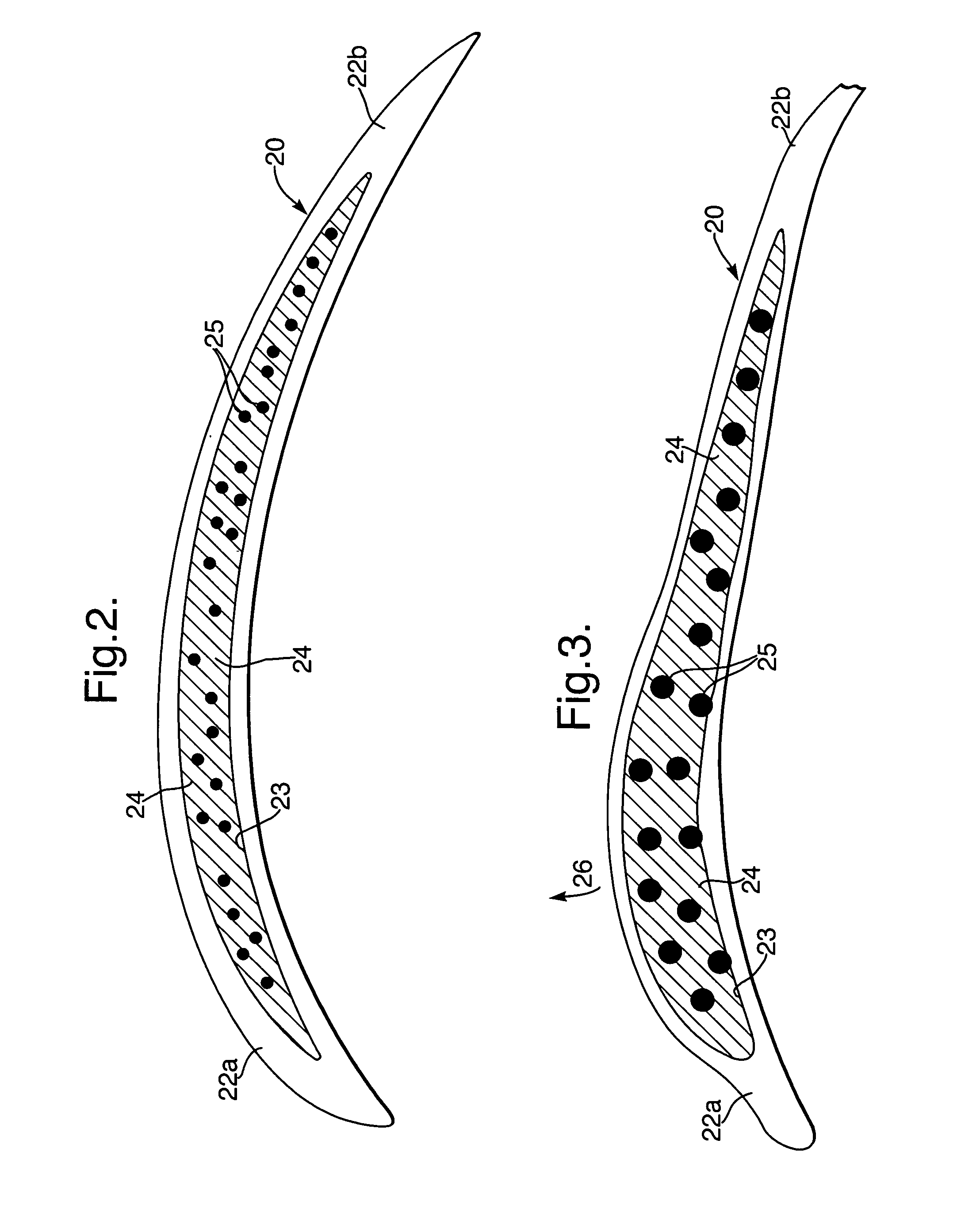
[0018]Referring to FIG. 2 illustrating a schematic cross-section of a fan blade 20 in accordance with the present invention. This fan blade 20 comprises a hollow aerofoil 22 in which a cavity 23 is filled with a matrix 24. Typically, the aerofoil 22 is made from titanium alloy panels, for example T16A14V alloy appropriately secured together. The matrix 24 is generally elastomeric and acts as a damping medium for the fan blade 20. Within the matrix 24 a number of capsules or elements 25 are appropriately located and distributed.

[0019]The fan blade 20 as configured in FIG. 2 is shown prior to a percussive impact. Thus, the fan blade 20 is consistent with the fan blade as installed within a gas turbine engine.

[0020]Referring to FIG. 3 illustrating a schematic cross-section of the fan blade 20 subsequent to a percussive impact such as a bird strike. Thus, the blade 20 comprises an aerofoil 22 within which the cavity 23 is filled by the matrix 24 but in the after percussive impact config...


PUM


Abstract

Percussive impacts due to bird strikes upon the hollow fan blades 20 are a well known problem. These percussive impacts not only deform previous fan blades but also reduce their stiffness. In accordance with the present invention, hollow fan blades 20 incorporate a cavity 23 within which, a matrix 24 with embedded expandable elements 25, is located. Thus, upon a percussive impact these expandable elements 25 are released in order to create an internal pressure within the cavity 25 which acts outwardly in order to relieve deformation and also stiffen the blade 20 as a result of the over pressure within the cavity 23.

Description

FIELD OF THE INVENTION[0001]The present invention relates to blades and more particularly to hollow fan blades used in gas turbine engines.BACKGROUND OF THE INVENTION[0002]Referring to FIG. 1, a gas turbine engine is generally indicated at 10 and comprises, in axial flow series, an air intake 11, a propulsive fan 12, an intermediate pressure compressor 13, a high pressure compressor 14, combustion equipment 15, a high pressure turbine 16, an intermediate pressure turbine 17, a low pressure turbine 18 and an exhaust nozzle 19.[0003]The gas turbine engine 10 works in a conventional manner so that air entering the intake 11 is accelerated by the fan 12 which produce two air flows: a first air flow into the intermediate pressure compressor 13 and a second air flow which provides propulsive thrust. The intermediate pressure compressor compresses the air flow directed into it before delivering that air to the high pressure compressor 14 where further compression takes place.[0004]The comp...

Claims


Application Information

Patent Timeline
IPC IPC(8): B64C11/16F01D5/14F01D5/16F01D5/18F04D29/38F04D29/66
CPCF01D5/147F01D5/16F01D5/18F04D29/668F04D29/388Y02T50/676Y02T50/671Y02T50/60
Inventor WHITEHEAD, CHRISTOPHER MREAD, SIMON
Owner ROLLS ROYCE PLC
Why Eureka
Try Eureka