Extrusion die for making a double-skin honeycomb substrate

a honeycomb substrate and extruder technology, applied in the field of honeycomb substrates, can solve the problems of reducing the isostatic strength causing bending moments and undesirable tensile stresses, and affecting the quality of the honeycomb substrate,

Inactive Publication Date: 2006-09-26
CORNING INC
View PDF16 Cites 26 Cited by
  • Summary
  • Abstract
  • Description
  • Claims
  • Application Information

AI Technical Summary

Benefits of technology

[0010]In another aspect, the invention relates to an extrusion die assembly for making a double-skin honeycomb substrate which comprises an inner cell forming die having a central region and a peripheral region. The central region comprises an array of inner slots cut to define an array of inner pins and an array of central feedholes in communication with the array of inner slots. The peripheral region comprises an array of peripheral feedholes. The extrusion die assembly further includes a skin forming mask mounted coaxially with the inner cell forming die. The extrusion die assembly further includes at least one outer cell forming die mounted coaxially with and interposed between the inner cell forming die and the skin forming mask. The outer cell forming die has an array of outer slots cut to define an array of outer pins. The outer pins are spaced radially from the central region to define an inner skin slot and spaced radially from the skin forming mask to define an outer skin slot. The inner skin slot is in selective communication with the array of peripheral feedholes. The outer skin slot is in selective communication with the peripheral feedholes through an opening in the outer cell forming die.

Problems solved by technology

In this state, the webs are subjected to high deflections, which generate bending moments and undesirable tensile stresses in the honeycomb substrate.
Although reduction in web thickness has improved emissions performance, it has also resulted in marked reduction in the isostatic strength of the honeycomb substrate, making the honeycomb substrate more susceptible to damage during canning and lowering the thermal and mechanical durability of the honeycomb substrate in the application.
While these approaches can improve the isostatic strength of the honeycomb substrate, they can also yield undesirable results such as increase in pressure loss across the honeycomb substrate and / or reduction in thermal shock strength of the honeycomb substrate.

Method used


Image

  • Extrusion die for making a double-skin honeycomb substrate
  • Extrusion die for making a double-skin honeycomb substrate
  • Extrusion die for making a double-skin honeycomb substrate

Examples


Embodiment Construction

[0028]The invention will now be described in detail with reference to a few preferred embodiments, as illustrated in the accompanying drawings. In the following description, numerous specific details are set forth in order to provide a thorough understanding of the invention. It will be apparent, however, to one skilled in the art, that the invention may be practiced without some or all of these specific details. In other instances, well-known features and / or process steps have not been described in detail in order to not unnecessarily obscure the invention. The features and advantages of the invention may be better understood with reference to the drawings and discussions that follow.

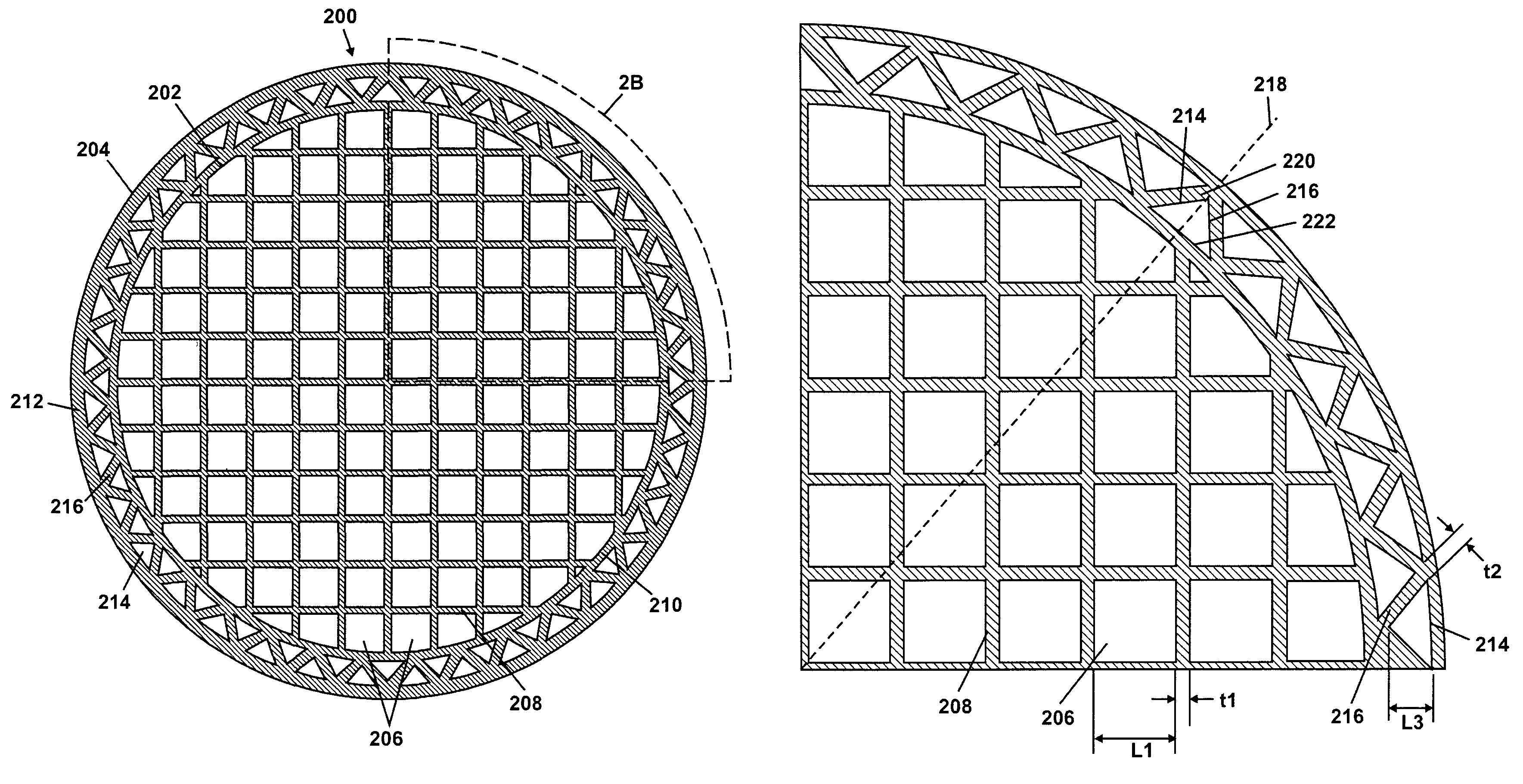
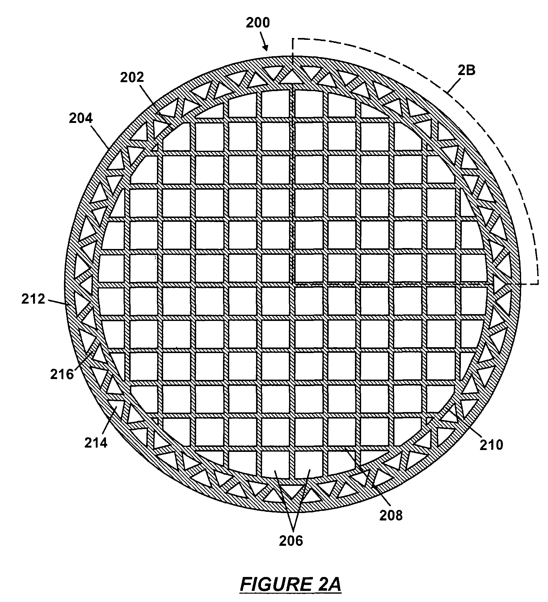
[0029]While not wishing to be bound by theory, the inventors believe herein that the isostatic strength of a honeycomb substrate can be enhanced by incorporating reinforcing webs near the periphery of the honeycomb substrate. The inventors propose a double-skin structure whereby the reinforcing webs ar...


PUM

PropertyMeasurementUnit
thicknessaaaaaaaaaa
radiusaaaaaaaaaa
pressureaaaaaaaaaa

Abstract

A honeycomb substrate includes an inner body having an inner skin and an array of inner webs defining an array of inner cells within the inner skin. The honeycomb substrate further includes an outer body having an outer skin formed concentric with the inner skin and an array of outer webs defining an array of triangle cells between the inner skin and the outer skin. The triangle cells are oriented along a radial direction with respect to a center of the inner body. An extrusion assembly for forming the honeycomb substrate includes an inner cell forming die, an outer cell forming die, and a skin forming mask, all mounted coaxially. An outer skin slot formed between the outer cell forming die and the skin forming mask is in communication with feedholes in the inner cell forming die through an opening in the outer cell forming die.

Description

BACKGROUND OF INVENTION[0001]The invention relates generally to honeycomb substrates and particularly to a method of enhancing the isostatic strength of a honeycomb substrate having cells defined by thin webs.[0002]Honeycomb substrates are widely used as catalyst carriers for purification of exhaust gases from internal combustion engines. A typical honeycomb substrate has a columnar body, the cross-sectional shape of which is typically round or oval. An array of parallel, straight channels is formed in the columnar body to allow passage of gases through the honeycomb substrate. The channels run axially along the length of the columnar body. The cross-section of the channels can be of any arbitrary shape, such as triangle, square, and hexagon. For automotive applications, the cross-section of the channels is frequently square because square channels are easier to manufacture. The channel walls may be coated with a porous washcoat containing an active catalyst. Alternatively, the acti...

Claims


Application Information

Patent Timeline
Patent Type & Authority Patents(United States)
IPC IPC(8): B29C47/12B29C48/30B29C48/11B29C48/32B32B3/02B32B3/12
CPCB29C47/0028B29C47/12B32B3/02B32B3/12Y10T428/24149B29L2031/60B29C48/32B29C48/11
Inventor BERNAS, JAMES J.BREW, THOMAS W.FROST, RODNEY I.HUMPHREY, MARK L.MIAO, WEIGUOMILLER, KENNETH R.SUN, YAWEITREACY, JR., DAVID R.WIDJAJA, SUJANTO
Owner CORNING INC
Why Eureka
Try Eureka