
Determination of acoustic velocity in bone

a technology of acoustic velocity and bone, applied in the field of non-invasive measurement, can solve the problems of inability to ignore soft tissue, inability to calculate acoustic bone velocity, and inability to accurately measure the acoustic bone velocity, etc., and achieve the effect of high spatial resolution

Inactive Publication Date: 2006-09-26
BEAM MED
View PDF35 Cites 68 Cited by
  • Summary
  • Abstract
  • Description
  • Claims
  • Application Information

AI Technical Summary

Benefits of technology

[0014]Another object of some preferred embodiments of the invention is to provide a measurement probe and / or a measurement method in which there is a minimum amount of interference between transmitting elements and receiving elements.
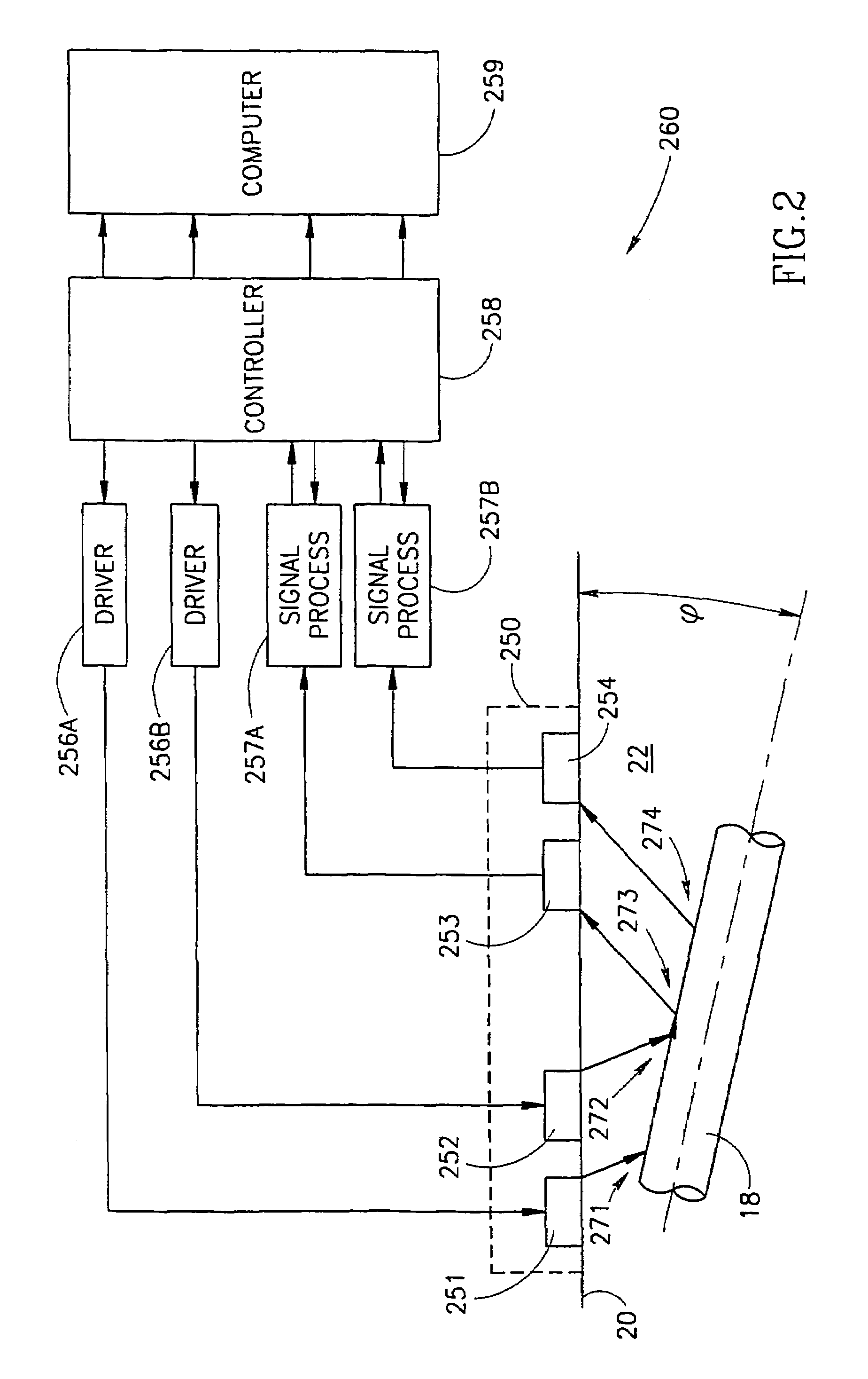
[0021]Another aspect of some preferred embodiments of the invention relates to reducing interference caused by cross talk between ultrasonic elements of a receiver / transmitter probe, especially for acoustic bone and / or soft tissue velocity determination. In a preferred embodiment of the invention, the probe design presents a labyrinth to waves which travel through the probe, between ultrasonic elements of the probe. Thus, such wave may be delayed. Additionally or alternatively, spaces between such ultrasonic elements are filled with acoustically slow materials and / or acoustically attenuating materials. This velocity reduction allows for time gating out the waves which travel through the probe. Additionally or alternatively, electrical shielding is provided to shield receivers from transmitters. This reduces electrical cross-talk.
[0022]In a preferred embodiment of the invention, an acoustic chamber between the ultrasonic elements and the body to be measured is formed of attenuating materials to reduce cross-talk between the ultrasonic elements. Alternatively or additionally, the chamber is filled with acoustically slow materials.

Problems solved by technology

Unfortunately, the thickness of the soft tissue varies along the length of the bone.
Generally, the soft tissue cannot be ignored.
In addition, the propagation paths between the bone and the receivers are not the same for the reflected wave and for the wave from the transmitter, so the calculated acoustic bone velocity may not be correct.
Second, the above-described method requires a relatively long portion of flat bone.
Thus, only a small number of bones can be tested, using this method, such as the tibia.
In addition, since high frequency ultrasonic waves are very lossy, it is not practical to use them for this method.

Method used


Image

  • Determination of acoustic velocity in bone
  • Determination of acoustic velocity in bone
  • Determination of acoustic velocity in bone

Examples


Embodiment Construction

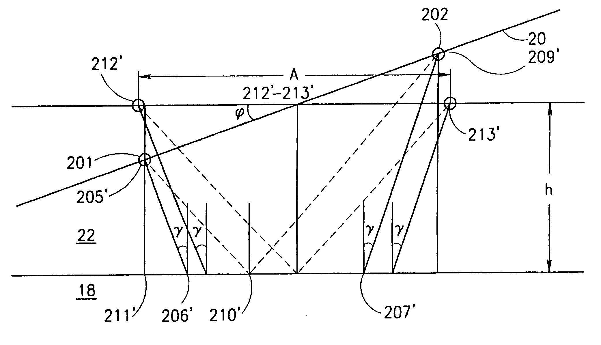
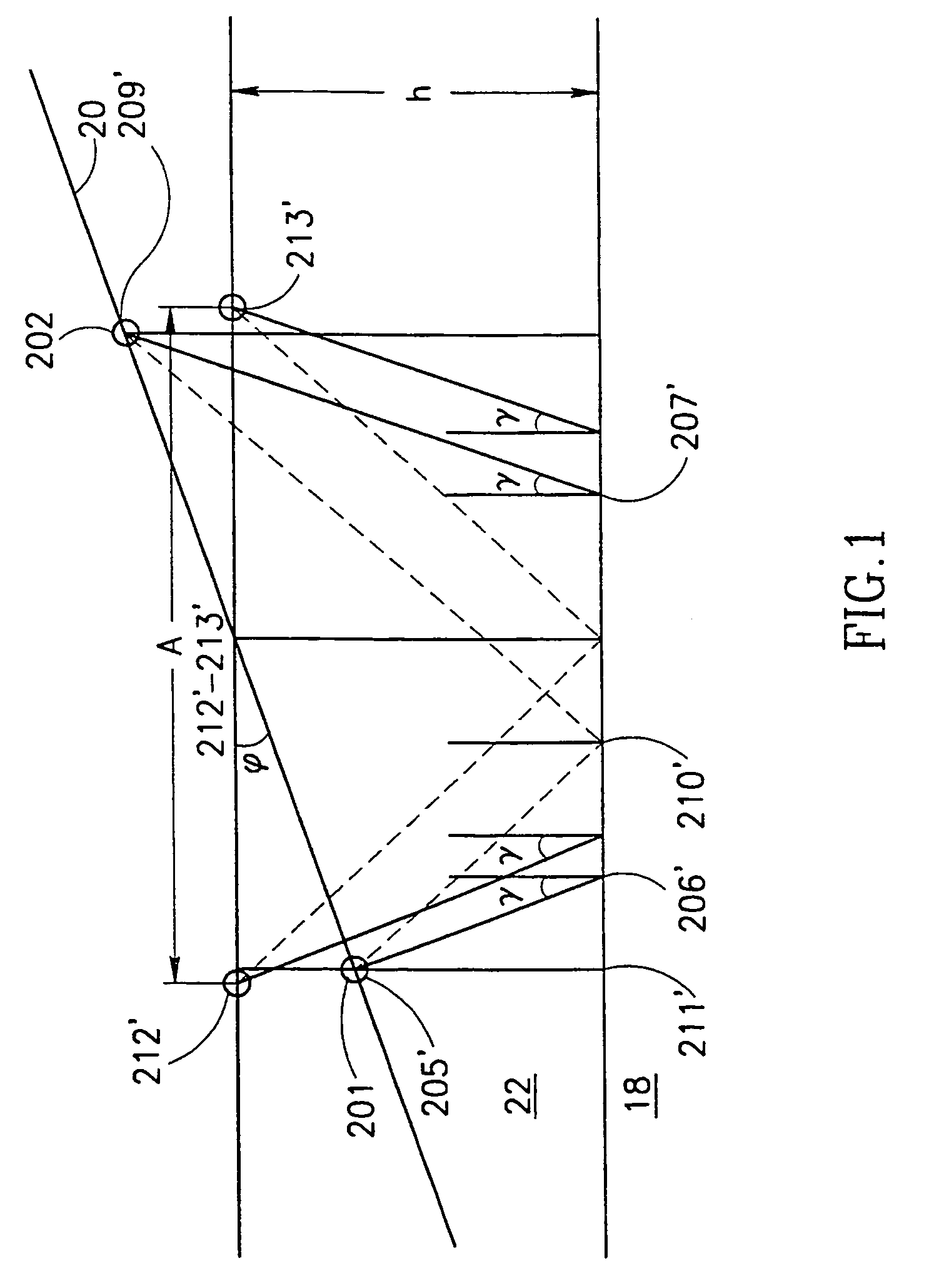
[0134]FIG. 1 illustrates a simplified situation in which an acoustic bone velocity of a bone 18 is to be measured through an intervening soft tissue layer 22. An ultrasonic wave is generated by an ultrasonic element 201 (a transmitter) and detected by an ultrasonic element 202 (a receiver). There are many paths that the ultrasonic wave can and does take between the two ultrasonic elements. However, each path has different attributes. In particular, one path is the fastest path. In a preferred embodiment of the invention, the fastest path includes a bone segment.

[0135]φ is defined as the angle between the line connecting the two ultrasonic elements and a line parallel to the surface of bone 18. h is defined as the average distance between the ultrasonic elements and bone 18. A skin 20, which defines the surface of soft tissue 22 is usually flush with probe 250. Considering the configuration in which φ≠0, elements 201 and 202 are situated at positions 205′ and 209′ respectively, the t...


PUM


Abstract

A method for determining an acoustic velocity in a segment of a bone covered with a layer of soft tissue having an outer surface, which includes determining a first travel time of a first ultrasonic wave along a first path from the outer surface back to the outer surface which path includes at least a first part of the bone segment together with determining a second travel time of a second ultrasonic wave along a second path from the outer surface back to the outer surface, which path includes at least a second part of the bone segment and also determining a third travel time of a third ultrasonic wave along a third path from the outer surface back to the outer surface which path includes at least a third part of the bone segment, and deriving the acoustic velocity in the segment of bone from the three determined travel times.

Description

[0001]This application is a 371 of PCT / IL98 / 00299 filed Jun. 24, 1998, which application is a US national filing of PCT Application PCT / IL98 / 00299, filed Jun. 24, 1998, and claims the benefit of U.S. Provisional patent application No. 60 / 076,698, filed Mar. 3, 1998, the disclosure of which is incorporated herein by reference.FIELD OF THE INVENTION[0002]The present invention relates to non-invasive measurement of the mechanical properties of bone and especially to measurement at arbitrary angles relative to the bone.BACKGROUND OF THE INVENTION[0003]It is known in the art that the velocity of a sound wave in a material depends on the mechanical properties of the material.[0004]A sound wave that reaches a solid at an angle will typically propagate through and along the solid as a combination of three waves, namely, longitudinal, transverse and surface waves, wherein each wave has a different velocity. In bone velocity determination, the longitudinal wave, which is the fastest, is usual...

Claims


Application Information

Patent Timeline
IPC IPC(8): A61B8/02
CPCA61B8/0875G01S15/8925G01H5/00A61B8/4227
Inventor KANTOROVICH, EDWARDPASTERNAK, VLADIMIRASHKENAZI, SHAILEDENEV, ELENAMORDVINOV, ANDREYNIV, YEHUDA
Owner BEAM MED
Learn More