Voltage source circuit with selectable temperature independent and temperature dependent voltage outputs

a voltage output and voltage technology, applied in the direction of dc-amplifiers with dc-coupled stages, different amplifiers, instruments, etc., can solve the problem of not being able to provide an output voltage having different characteristics, and achieve the effect of improving performance and/or operational flexibility

Active Publication Date: 2006-09-26
ANALOG DEVICES INC
View PDF9 Cites 43 Cited by
  • Summary
  • Abstract
  • Description
  • Claims
  • Application Information

AI Technical Summary

Benefits of technology

[0013]Several variations to the basic embodiment are described which provide enhanced performance and / or operational flexibility. In a preferred embodiment, a fourth switch is added and operated such that the amplifier's input offset voltage is substantially eliminated from Vout.

Problems solved by technology

However, it is unable to provide an output voltage having different characteristics, should such a voltage be needed by a particular application.

Method used


Image

  • Voltage source circuit with selectable temperature independent and temperature dependent voltage outputs
  • Voltage source circuit with selectable temperature independent and temperature dependent voltage outputs
  • Voltage source circuit with selectable temperature independent and temperature dependent voltage outputs

Examples


Embodiment Construction

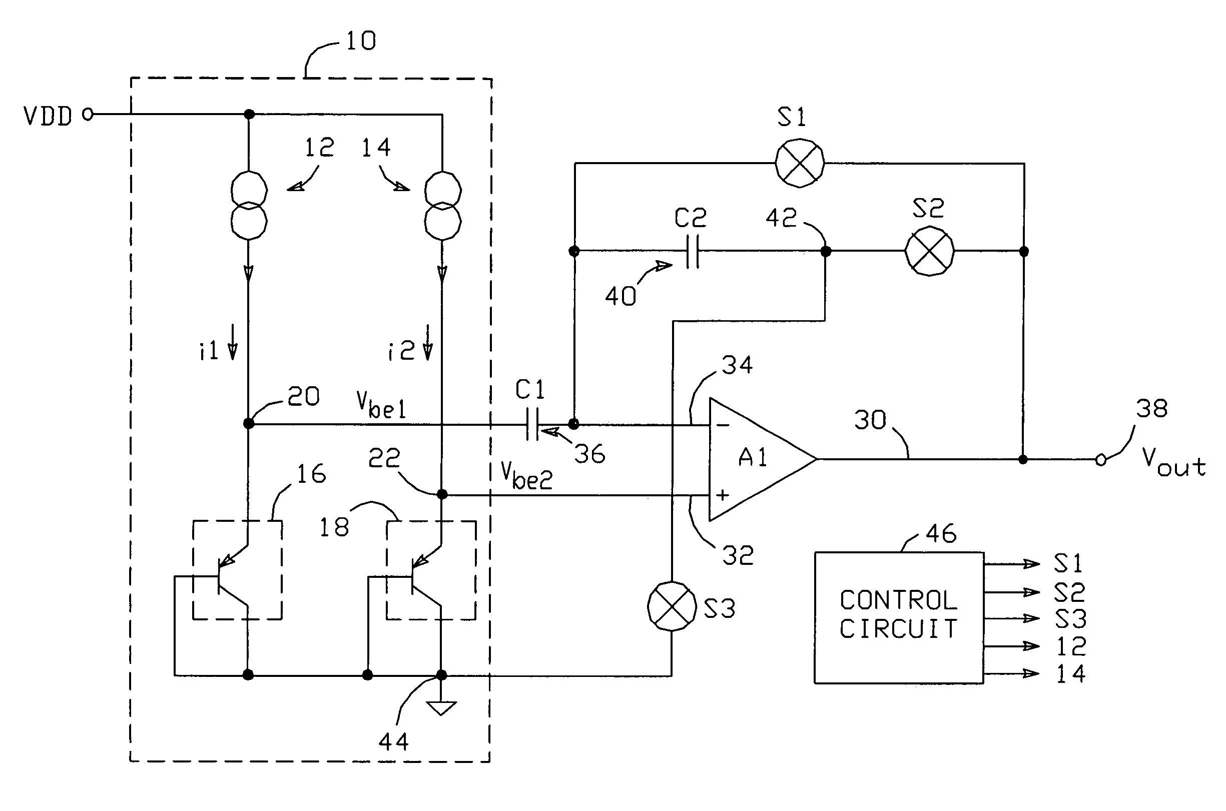
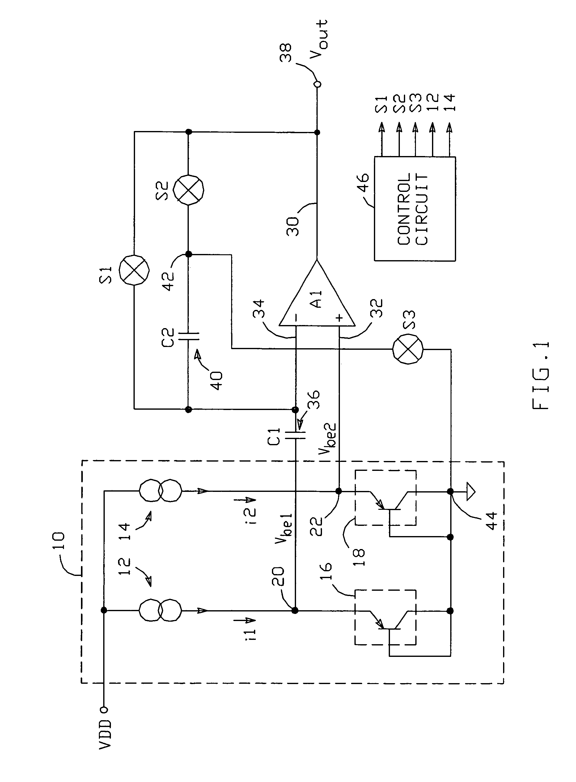
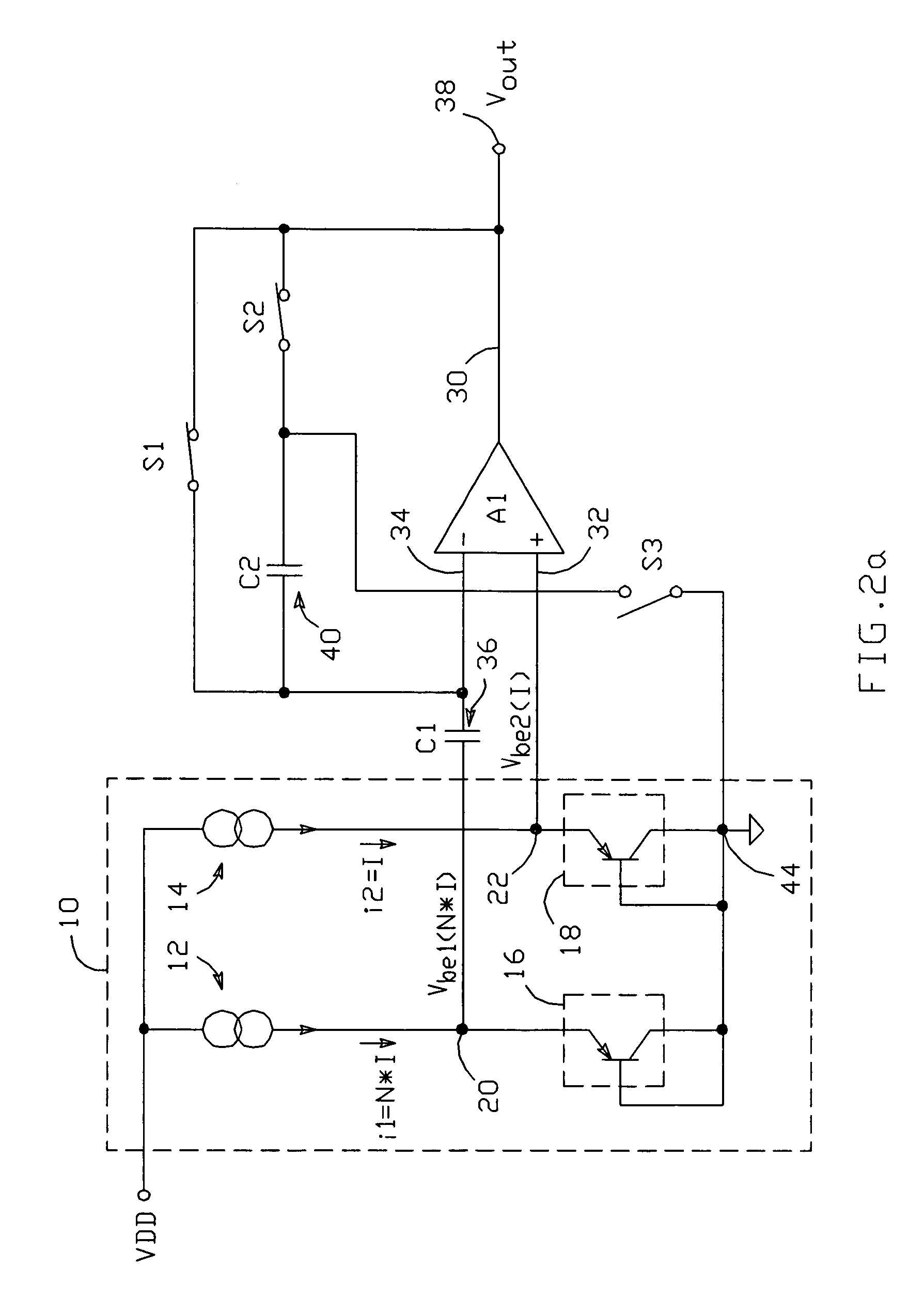
[0025]A basic embodiment of a voltage source circuit capable of selectively providing a temperature independent or temperature dependent output voltage is shown in FIG. 1. The present voltage source circuit includes a “base-emitter voltage generating circuit”10, which comprises first and second current sources (12, 14) which provide first and second currents (i1, i2), respectively, and first and second pn junctions (16, 18) connected to conduct i1 and i2, respectively, and thereby establish first and second base-emitter voltages Vbe1 and Vbe2 at first and second nodes 20 and 22, respectively. Generating circuit 10 is arranged such that Vbe1 can be selectively set to a first value Vbe1(I) or a second value Vbe1(N*I), and such that Vbe2 can be selectively set to a first value Vbe2(I) or a second value Vbe2(N*I). This is preferably accomplished by making current sources 12 and 14 variable, such that each of currents i1 and i2 can be set to a value I or a value N*I.

[0026]The voltage sou...


PUM


Abstract

A voltage source includes first and second pn junctions which conduct the outputs of respective current sources to establish respective base-emitter voltages Vbe1 and Vbe2 at respective nodes; Vbe1 and Vbe2 can each be generated with a current I or a current N*I. An amplifier A1 has its non-inverting input connected to the second node and its inverting input connected to the first node through an input capacitor; a feedback capacitor is connected between the inverting input and a third node. Switches are connected between A1's inverting input and A1's output, between the third node and A1's output, and between the third node and a circuit common point. A control circuit operates the switches and current sources during first and second operating phases to selectively produce a temperature independent output voltage or a temperature dependent output voltage.

Description

[0001]This application claims the benefit of provisional patent application No. 60 / 540,704 to Daly et al., filed Jan. 30, 2004.BACKGROUND OF THE INVENTION[0002]1. Field of the Invention[0003]This invention relates to the field of voltage source circuits, and particularly to voltage source circuits capable of producing multiple output voltages having different characteristics.[0004]2. Description of the Related Art[0005]Voltage source circuits, which provide one or more output voltages, are well-known. Typically, such a circuit produces one or more output voltages, all of which have similar characteristics. For example, a voltage source might provide a temperature independent output voltage. Alternatively, an output voltage which is proportional to temperature might be provided. The desired characteristics of the circuit's output voltage would be determined based on the application for which the voltage is used.[0006]One voltage source circuit which provides a temperature independent...

Claims


Application Information

Patent Timeline
Patent Type & Authority Patents(United States)
IPC IPC(8): G05F3/16G05F1/10H03F3/45G05F3/30H02M5/42
CPCG05F3/30
Inventor DALY, MICHAEL P.MIRANDA, EVALDO M.THOMSON, DAVIDBROKAW, A. PAUL
Owner ANALOG DEVICES INC
Why Eureka
Try Eureka