GMR sensor with flux concentrators

a flux concentrator and gmr sensor technology, applied in the direction of electrical/magnetically converting sensor output, galvano-magnetic devices, instruments, etc., can solve the problems of difficult detection above ambient noise, small output signal, and poor signal-to-noise ratio, so as to increase the dynamic range of proximity sensors and minimize the effect of any misalignmen

Active Publication Date: 2006-09-26
HONEYWELL INT INC
View PDF13 Cites 80 Cited by
  • Summary
  • Abstract
  • Description
  • Claims
  • Application Information

AI Technical Summary

Benefits of technology

[0007]In some embodiments, the first and second magnetoresistive resistors are Giant Magneto Resistive (GMR) resistors, and may only be sensitive to the bias magnetic field component that is in the plane of the proximity sensor. In some embodiments, flux concentrators may be positioned proximate to each of the first and second magnetoresistive resistors. The flux concentrators may help redirect or shunt the magnetic field component produced by the bias magnet source that is perpendicular to the direction of motion of the target through the first and second magnetoresistive resistors in a direction that is parallel to the direction of motion of the target. This may help improve the sensitivity and increase the dynamic range of the proximity sensor, and may further help minimize the effect of any misalignment between the biasing magnetic and the proximity sensor, and between the proximity sensor and the ferrous target. In some cases, four or more resistors are used, and may be connected in a full bridge configuration.

Problems solved by technology

However, for lower gear teeth speeds, the voltage generated is often small and difficult to detect above the ambient noise.
However, this increase in the detected field relative to the fixed level is often small, which can result in a relatively small output signal and a relatively poor signal to noise ratio.

Method used


Image

  • GMR sensor with flux concentrators
  • GMR sensor with flux concentrators
  • GMR sensor with flux concentrators

Examples


Embodiment Construction

[0015]The following description should be read with reference to the drawings, in which like elements in different drawings are numbered in like fashion. The drawings, which are not necessarily to scale, depict selected embodiments and are not intended to limit the scope of the invention. Although examples of construction, dimensions, and materials may be illustrated for the various elements, those skilled in the art will recognize that many of the examples provided have suitable alternatives that may be utilized.

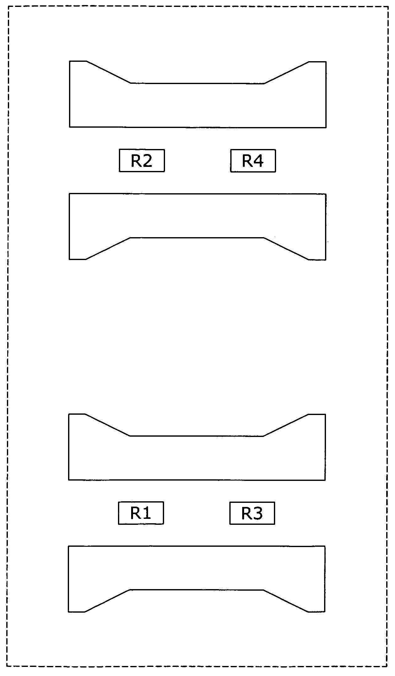
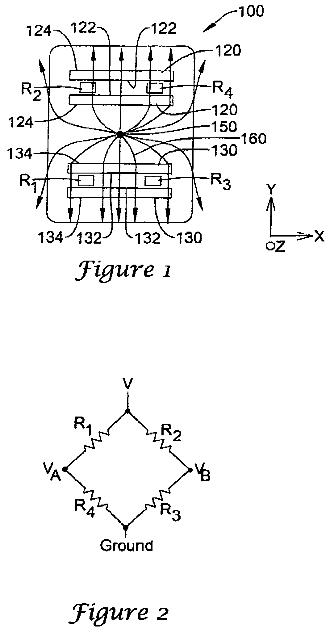
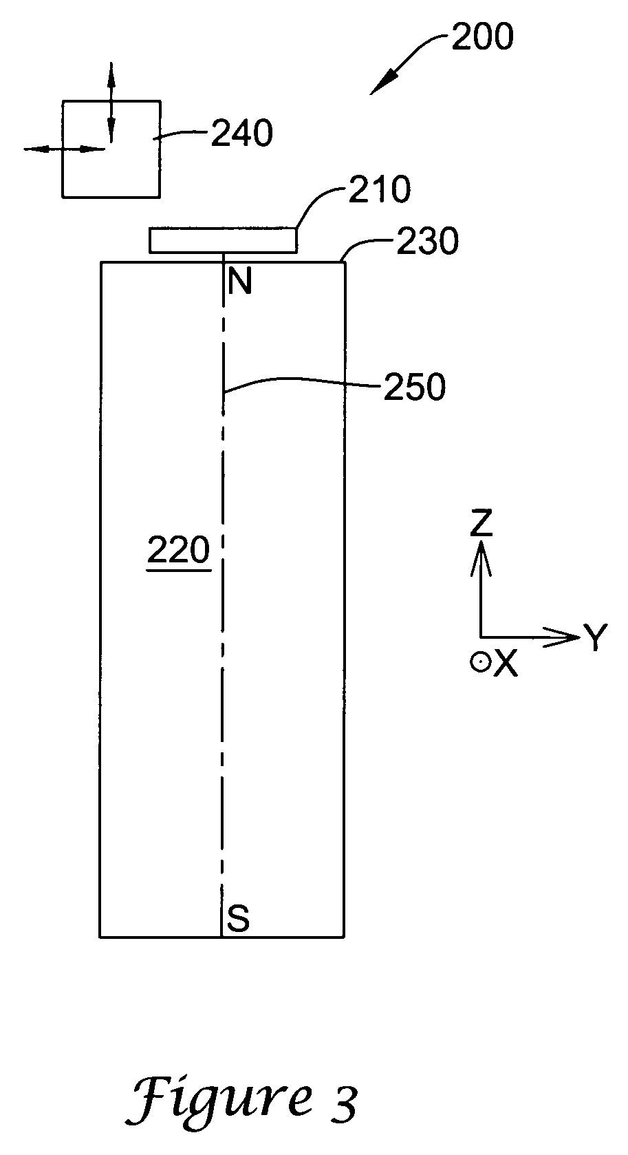
[0016]The present invention provides a proximity sensor. In some embodiments, the invention uses magnetoresistive resistor made from a Giant Magneto-Resistive (GMR) material that are configured in a sensing bridge. In some cases, the GMR sensing bridge may be configured to minimize sensitivity in a standard axis. In other cases, the GMR sensing bridge may be configured to minimize sensitivity in a cross-axis axis. While the present invention is not so limited, an appreciati...


PUM


Abstract

A proximity sensor that is capable of producing a relatively larger output signal than past proximity sensors, and in some cases, an output signal that is relatively independent of the speed at which a target passes the sensor. In one illustrative embodiment, the proximity sensor includes a first magnetoresistive resistor and a second magnetoresistive resistor connected in a bridge configuration. The first magnetoresistive resistor is spaced from the second magnetoresistive resistor along the path of a moving ferrous target. A bias magnet source is positioned behind the proximity sensor, and the ferrous target passes in front of the proximity sensor. The ferrous target alters the direction of the bias magnetic field in the vicinity of the first and second magnetoresistive resistors as the ferrous target passes by the proximity sensor. Flux concentrators are positioned proximate to each of the first and second magnetoresistive resistors. The flux concentrators may help redirect or shunt the magnetic field component produced by the bias magnet source that is perpendicular to the direction of motion of the target through the first and second magnetoresistive resistors in a direction that is parallel to the direction of motion of the target.

Description

BACKGROUND OF THE INVENTION[0001]The present invention relates generally to proximity sensors and more particularly to proximity sensors that sense changes in a magnetic field in the plane of the sensing element.[0002]There has been, and continues to be, a need to do better magnetic detection of the location or proximity of a ferromagnetic object relative to a magnetic sensor. The need exists in a variety of commercial, industrial and automotive applications. For example, in some applications, there is a need to do better magnetic detection of the location or proximity of a passing gear tooth moving near the end of a probe type sensor. This is only one specific application, and there are numerous other applications that have a need detect the location or proximity of a ferromagnetic object relative to a magnetic sensor.[0003]A number of proximity sensing devices based on magnetic sensing have been utilized in the past. Variable reluctance sensors (VRS) have been used in which the mo...

Claims


Application Information

Patent Timeline
Patent Type & Authority Patents(United States)
IPC IPC(8): G01B7/30G01B7/14G01R33/02G01R33/09G01D5/14G01R33/06
CPCG01D5/145G01B7/14
Inventor BICKING, ROBERT E.
Owner HONEYWELL INT INC
Why Eureka
Try Eureka