Pulse generating circuit and sampling circuit

a pulse generation and sampling circuit technology, applied in pulse manipulation, pulse technique, pulse train generators, etc., can solve the problems of difficult to sample signals with high precision, and difficult to control the generation timing of pulses with high precision

a pulse generation and sampling circuit technology, applied in pulse manipulation, pulse technique, pulse train generators, etc., can solve the problems of difficult to sample signals with high precision, and difficult to control the generation timing of pulses with high precision

US7113013B2Inactive Publication Date: 2006-09-26ADVANTEST CORP

Image

  • Pulse generating circuit and sampling circuit
  • Pulse generating circuit and sampling circuit
  • Pulse generating circuit and sampling circuit

Examples


Embodiment Construction

[0019]The invention will now be described based on the preferred embodiments, which do not intend to limit the scope of the present invention, but exemplify the invention. All of the features and the combinations thereof described in the embodiment are not necessarily essential to the invention.

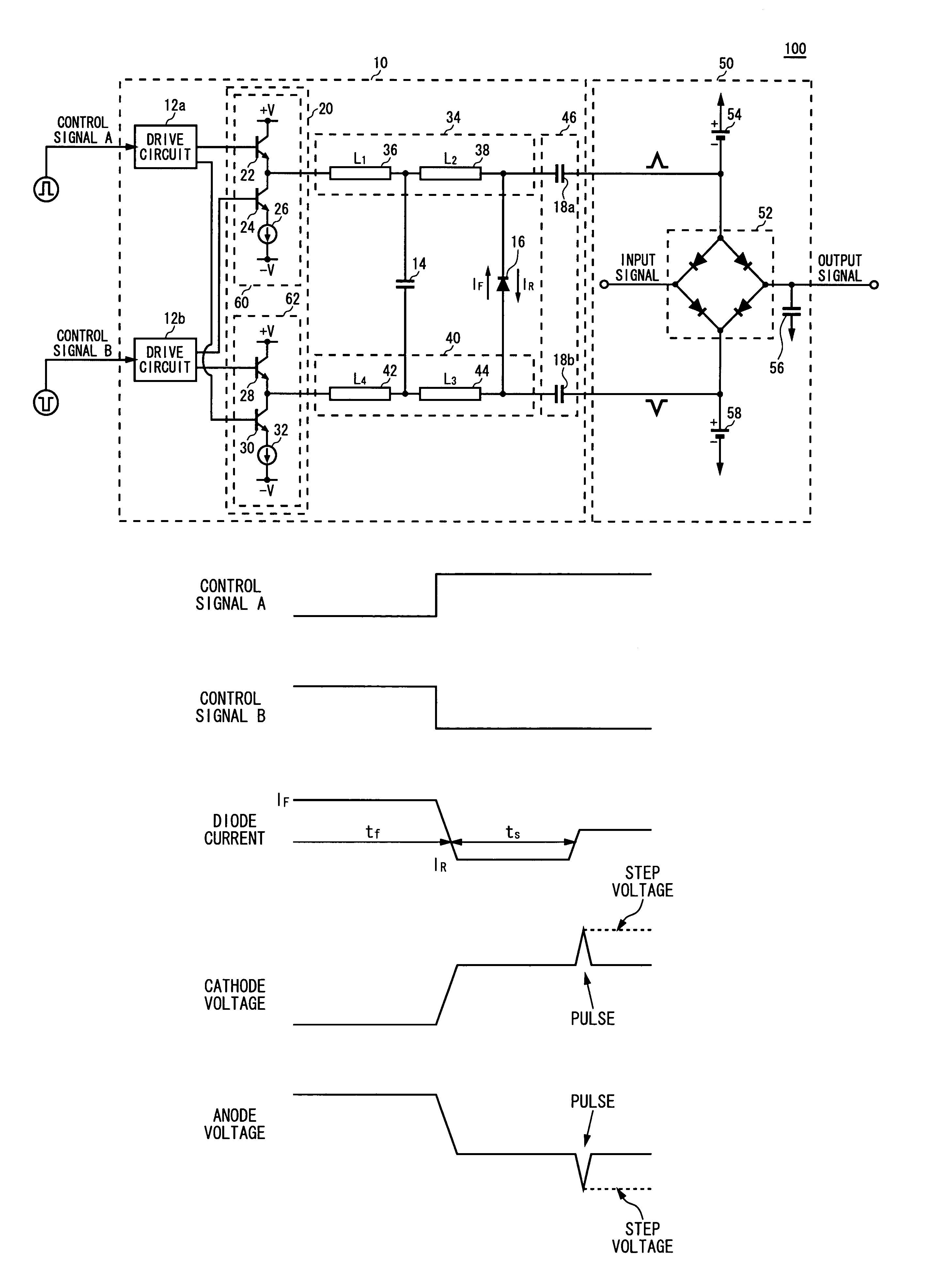
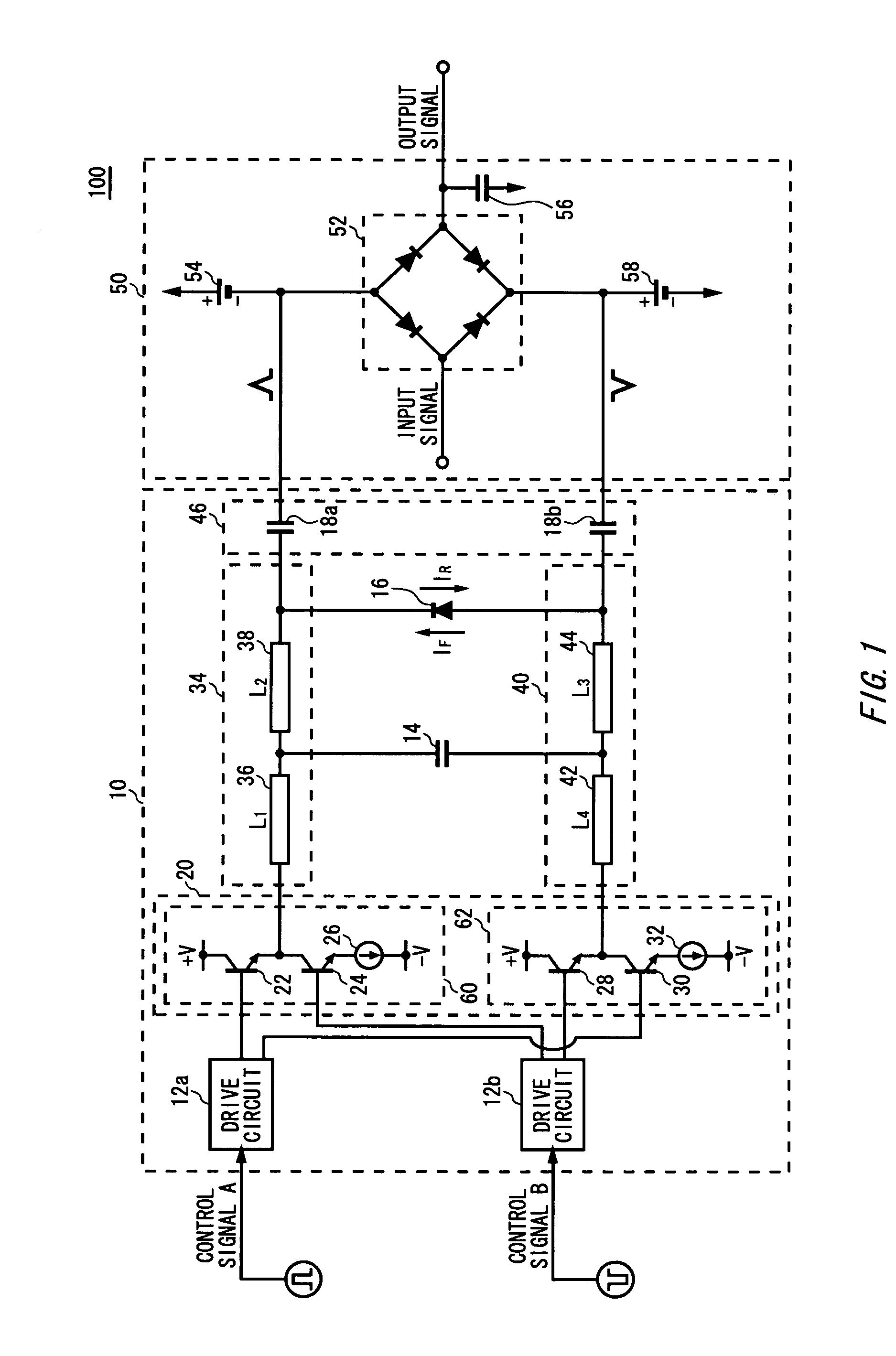
[0020]FIG. 1 is a view exemplary showing a configuration of a sampling circuit 100 according to the present invention. The sampling circuit 100 samples a given input signal at a predetermined timing. The sampling circuit 100 includes a pulse generating circuit 10 and a sampling unit 50.

[0021]The pulse generating circuit 10 generates pulses to determine timing at which input signals are sampled. The pulse generating circuit 10 includes drive circuits 12a and 12b, a bias unit 20, a step recovery diode 16, a cathode side transmission line 34, an anode side transmission line 40, a parallel capacitor 14, and a filter unit 46.

[0022]The drive circuits 12a and 12b receive control signals to generate ...


PUM


Abstract

There is provided a pulse generating circuit, which generates two pulses having a sign of amplitude different from each other, including: a step recovery diode of which electric potential of an anode and a cathode is respectively output as the pulses; a bias unit operable to select either a forward bias or a backward bias according to a given control signal and apply the selected bias to the step recovery diode; a forward current source operable to prescribe a forward current to be supplied to the step recovery diode when the forward bias is applied to the step recovery diode; and a backward current source operable to prescribe a backward current to be supplied to the step recovery diode when the backward bias is applied to the step recovery diode.

Description

CROSS REFERENCE TO THE RELATED APPLICATION[0001]The present application is a continuation application of PCT / JP2003 / 015066 filed on Nov. 26, 2003, which claims priority from a Japanese Patent application No. 2002-342873 filed on Nov. 26, 2002, the entire contents of which are incorporated herein by reference for all purposes.FIELD OF THE INVENTION[0002]The present invention relates to a pulse generating circuit that generates pulses and a sampling circuit that samples signals.DESCRIPTION OF THE RELATED ART[0003]Conventionally, a sampling circuit that samples signals includes a pulse generating circuit that generates pulses and a sampling unit that samples signals based on these pulses. For example, the sampling unit, which has a diode bridge, receives two pulses having a sign of amplitude different from each other and signals that should be sampled, and then samples the signals based on the received pulses. In this case, the pulse generating circuit that generates two pulses by mean...

Claims


Application Information

Patent Timeline
26 Sep 2006
Publication
US7113013B2
IPC
H03K5/01; H03K3/02; H03K3/36; H03K3/33; H03K17/00; H03K17/74
CPC
H03K17/74; H03K3/33
Inventors
KAWATA, AKIHIRO