Grid polarizer with suppressed reflectivity

a polarizer and reflectivity technology, applied in the field of polarizing optical elements, can solve problems such as unsatisfactory illumination returning to the sour

Inactive Publication Date: 2006-09-26
CORNING INC
View PDF112 Cites 89 Cited by
  • Summary
  • Abstract
  • Description
  • Claims
  • Application Information

AI Technical Summary

Problems solved by technology

One difficulty with this apparatus is that back-reflected light coming towards the laser suffers internal reflections in the grid polarizers that leads to undesirable illumination returning towards the source.

Method used


Image

  • Grid polarizer with suppressed reflectivity
  • Grid polarizer with suppressed reflectivity
  • Grid polarizer with suppressed reflectivity

Examples


Embodiment Construction

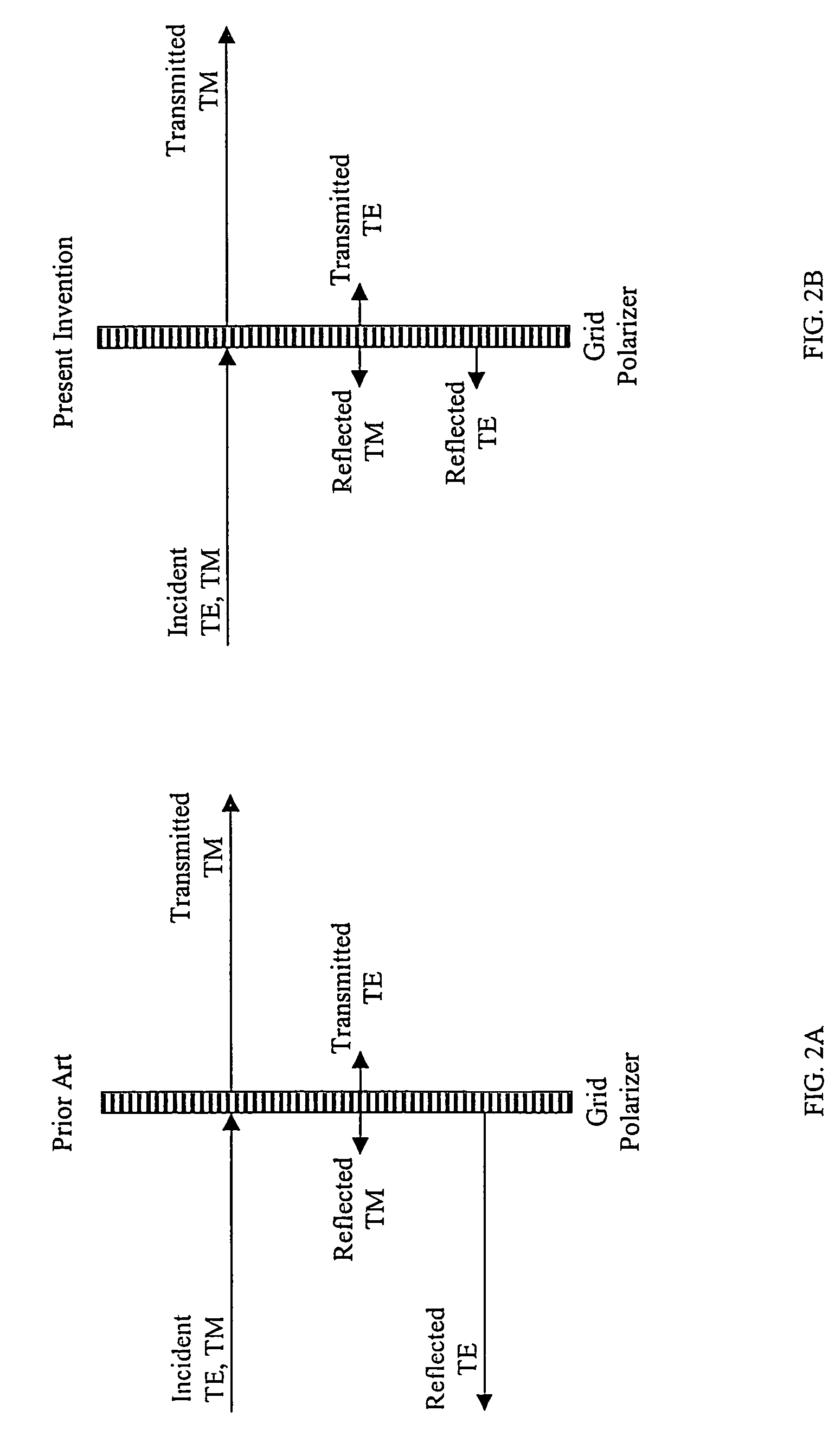
[0029]Prior art polarizers exhibit polarizing ability with high transmission a polarization component together coupled with high reflectivity of the orthogonal polarization component. The flow of electromagnetic energy is schematically illustrated on FIG. 2A for the current prior art and FIG. 2B for the present invention.

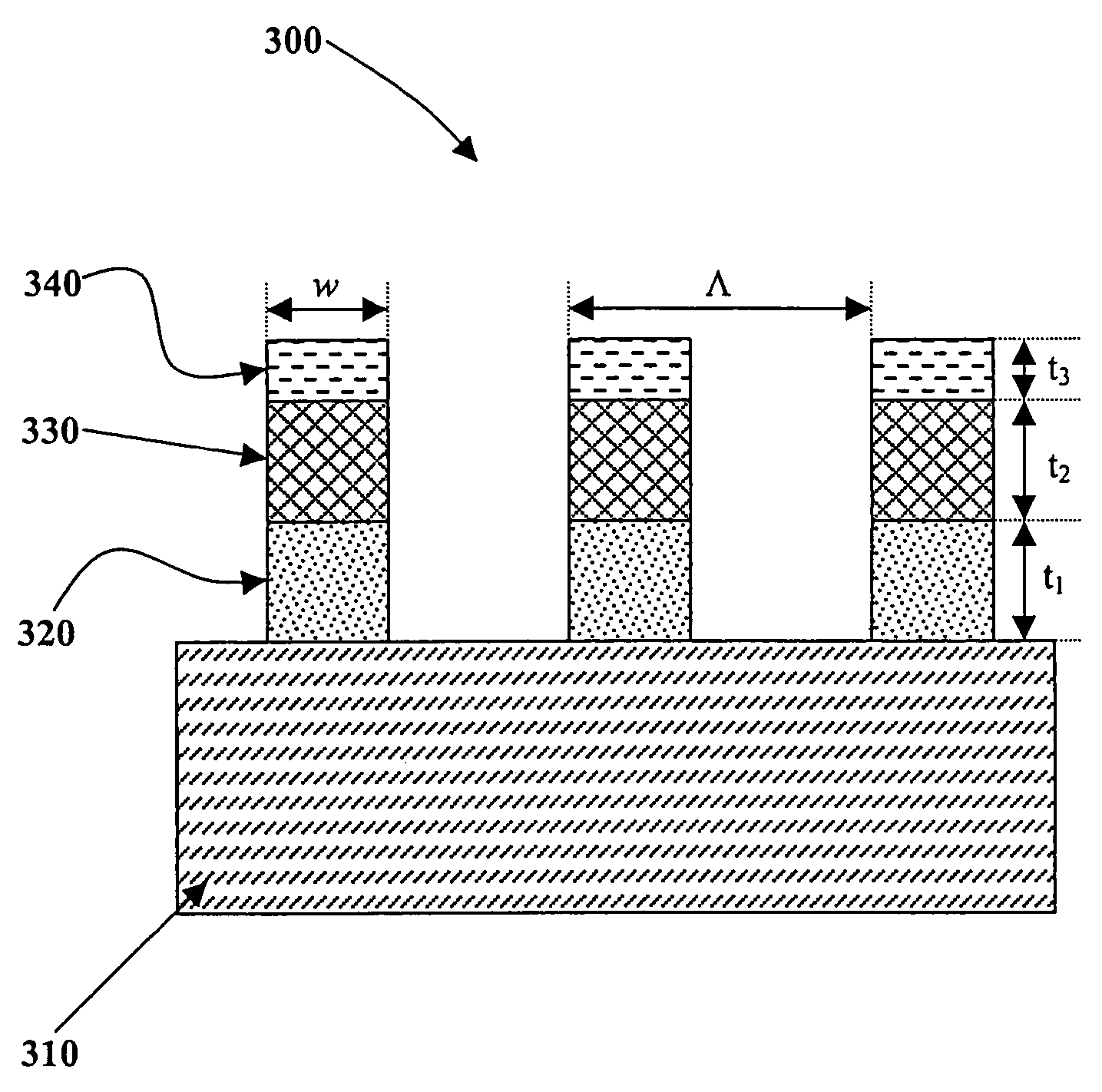
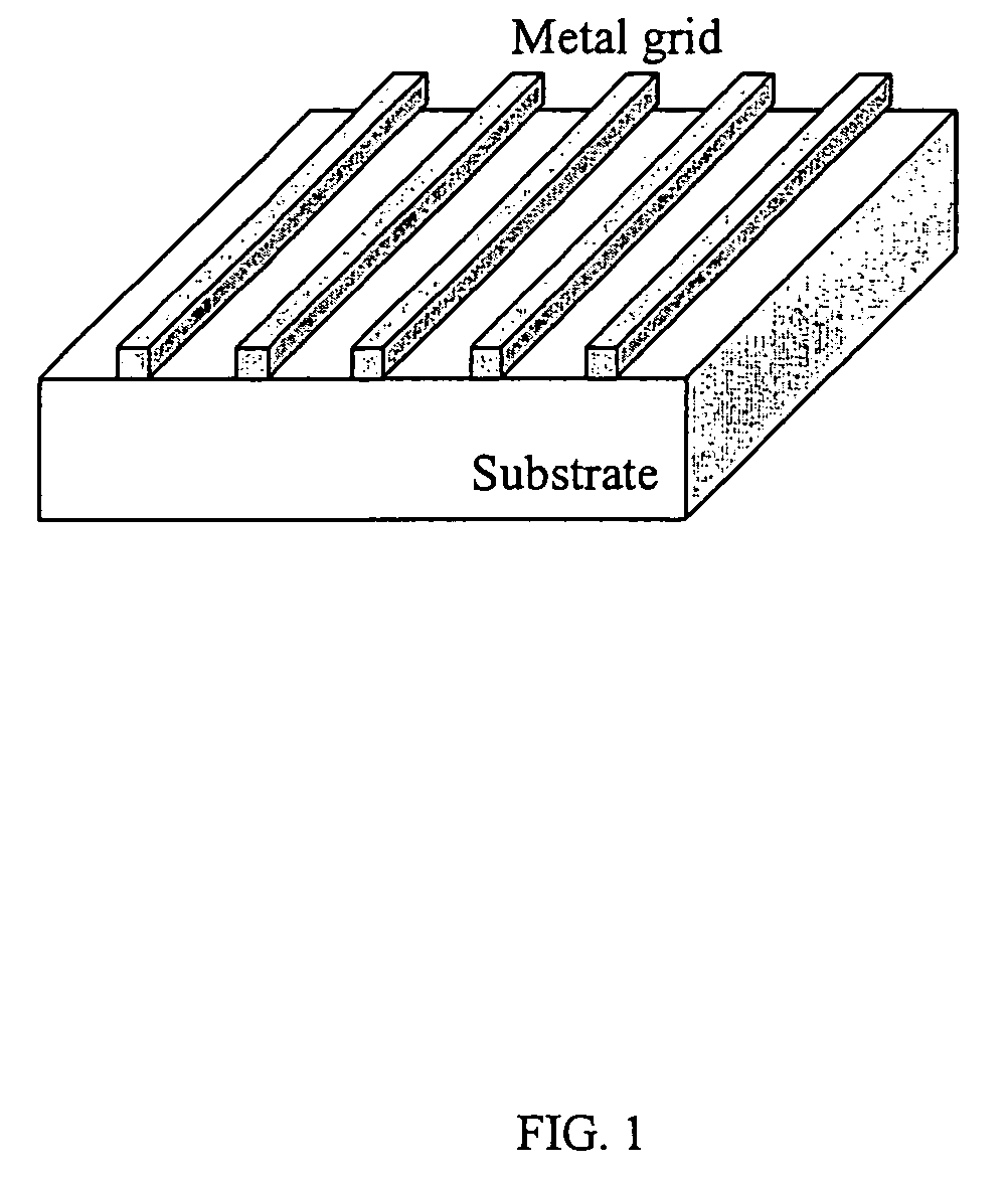
[0030]In general, the grid polarizer of the instant invention is comprised of a plurality of stacked materials (metal and dielectric) arranged as part of the repetition grid or as homogenous layers. Referring specifically now to FIG. 3, the grid polarizer 300 comprises a dielectric (generally glass) substrate 310 supporting a stack of metal and dielectric layers arranged as a parallel grid. Layer 320 is preferably made of a metallic material. Layer 330 is preferably made of a dielectric material. Layer 340 is preferably made of a metallic material. The medium of incidence that surrounds the grid is generally air (index of refraction equal to 1), although it can comp...


PUM


Abstract

Disclosed is a grid polarizer comprising a substrate; and a plurality of stacked metal and dielectric layers, having a width w, disposed on the substrate and forming a parallel grid of stacked layers. The stacked layers are spaced apart to form a repetition space between the stacked layers, such that no diffraction orders are allowed to propagate except the zero order. The grid polarizer that is capable of transmitting substantially all illumination of a given polarization while suppressing at least of portion of the illumination reflected due to an orthogonal polarization component.

Description

CROSS-REFERENCE TO RELATED APPLICATIONS[0001]This application claims the benefit of priority of U.S. Provisional Application Ser. No. 60 / 437,226 filed on Dec. 30, 2002, which is incorporated by reference herein in its entirety.FIELD OF THE INVENTION[0002]The present invention relates to polarizing optical elements for use in the visible portion of the electromagnetic spectrum. More particularly, the present invention relates to a highly efficient grid polarizing apparatus exhibiting improved transmitted illumination polarization contrast which is the result of the grid polarizing apparatus' ability to substantially suppress the reflection due to the orthogonal polarization component and thus the prevention of unwanted reflections back towards the illumination beam.BACKGROUND OF THE INVENTION[0003]Polarizing devices are of utilized in numerous optical systems and are commonly used in various applications such as liquid-crystal displays and optical isolators. The present invention rel...

Claims


Application Information

Patent Timeline
Patent Type & Authority Patents(United States)
IPC IPC(8): G02B5/30G02B27/28
CPCG02B5/3058
Inventor SALES, TASSO R.
Owner CORNING INC
Why Eureka
Try Eureka