
Mesh architecture for synchronous cross-connects

a synchronous cross-connect and mesh technology, applied in the field of communication networks, can solve the problems of incorporating undesirable characteristics of data routing through a network, and achieve the effects of easy scalable, easy fabrication, and high degree of automation

Inactive Publication Date: 2006-09-26
AVAGO TECH WIRELESS IP SINGAPORE PTE
View PDF15 Cites 19 Cited by
  • Summary
  • Abstract
  • Description
  • Claims
  • Application Information

AI Technical Summary

Benefits of technology

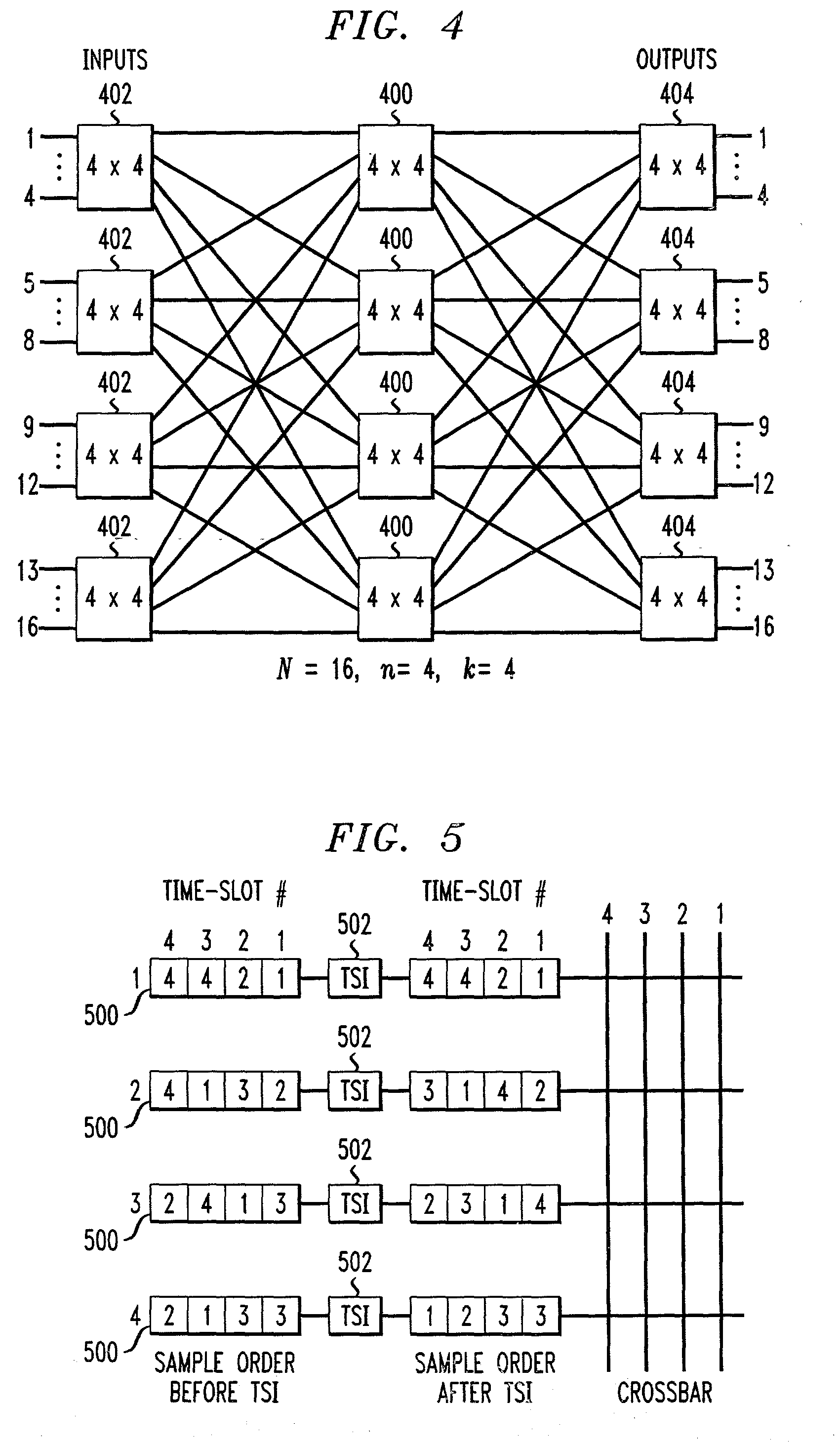
[0006]The present invention provides techniques for forming architectures for synchronous cross-connects. Techniques according to the invention exploit desirable and useful properties of a distributed mesh topology to provide a solution to conventional crossbar-based architectures. For example, the architectural complexity of the present invention increases only linearly with aggregate bandwidth, as compared to quadratically with a conventional crossbar architecture. Furthermore, the architecture of the invention is easily scalable, for example, by simply tiling primary functional blocks. The cross-connect architecture of the present invention requires only local communication and is therefore very amenable to fabrication on a semiconductor integrated circuit (IC) device. It is also optimal for area-based flip-chip input / output (I / O) packaging. Regularity in the design allows the architecture of the present invention to be scaled with process technology and to be easily extended to multi-chip implementations for forming multi-terabit systems.

Problems solved by technology

Each of the above techniques for routing data through a network, however, incorporate certain undesirable characteristics.

Method used


Image

  • Mesh architecture for synchronous cross-connects
  • Mesh architecture for synchronous cross-connects
  • Mesh architecture for synchronous cross-connects

Examples


Embodiment Construction

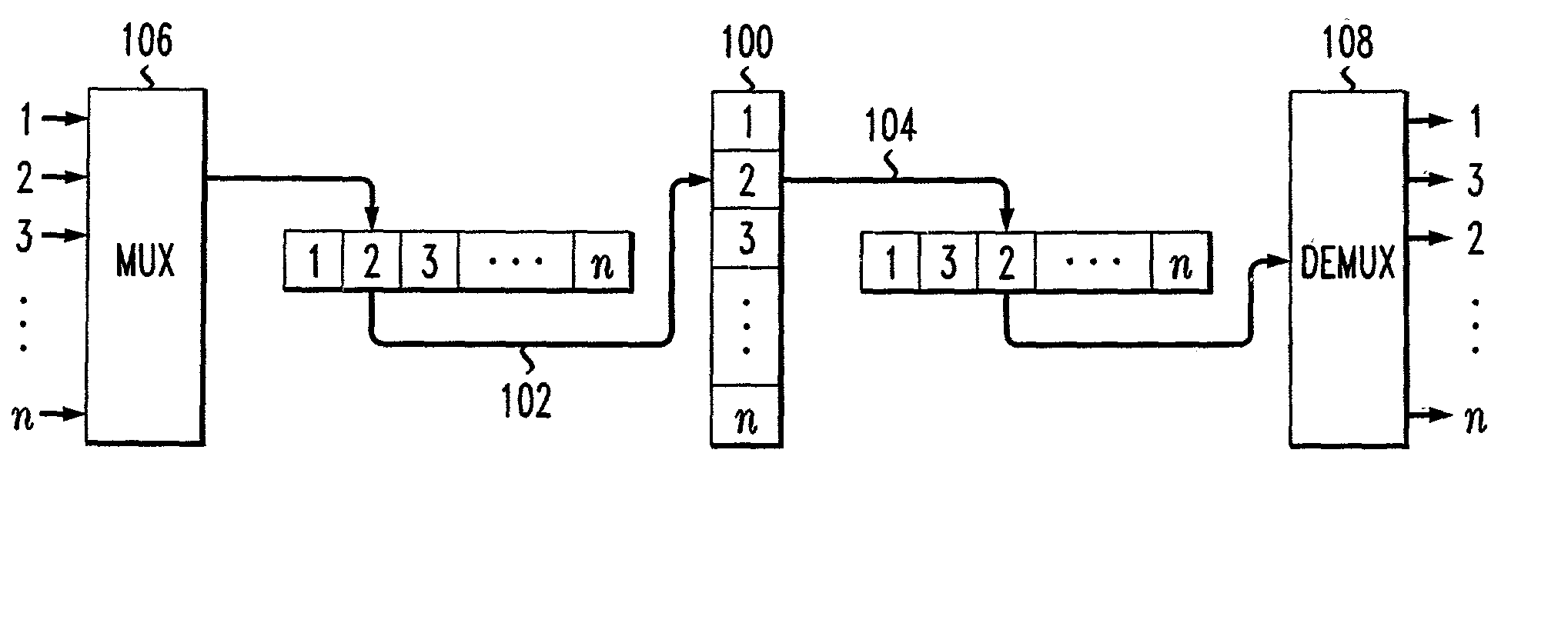
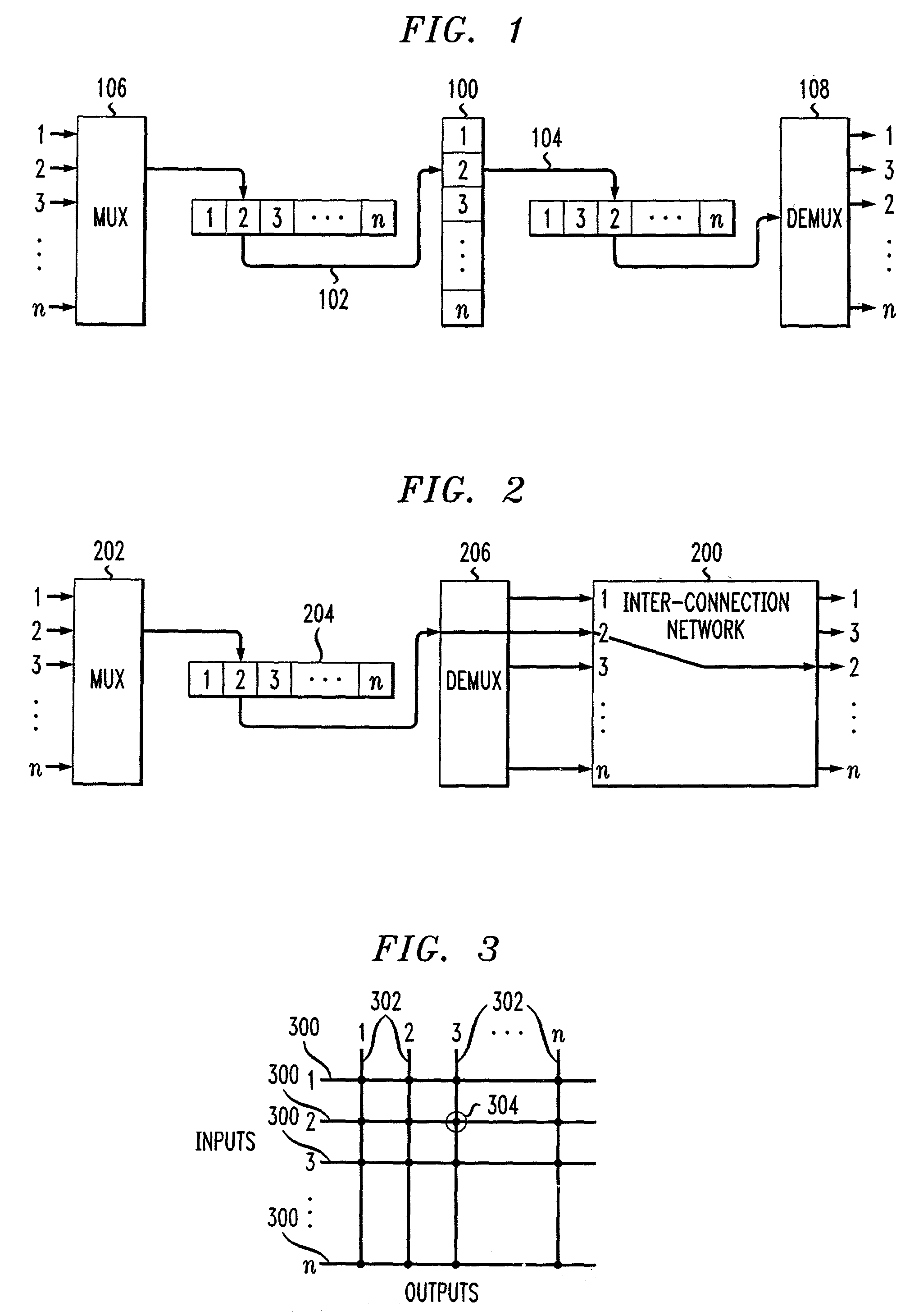
[0031]FIG. 1 illustrates a time-division switching or multiplexing scheme which includes a time-slot interchanger (TSI) 100. The TSI 100 is typically implemented as a buffer having a single input line 102 and a single output line 104, but these lines carry samples from n distinct channels that are multiplexed by a multiplexor (MUX) 106. The different order of samples on the output line 104, when passed through a demultiplexer (DEMUX) 108, results in the n samples being placed on corresponding output lines of the DEMUX 108. In essence, the TSI 100 switches samples by rearranging the order of the samples on a multiplexed line.

[0032]The process of reordering the samples is repeated every n clock cycles and is referred to as the period of the TSI. In practice, the TSI 100 is often comprised of two buffers, one buffer being used for reading data and another buffer being used for writing data during a given TSI period. At the completion of a TSI period, the TSI buffers switch function (i....


PUM


Abstract

A synchronous cross-connect switch for routing data samples from a source node to a destination node comprises a mesh architecture including a plurality of inputs for receiving one or more of the data samples presented to the cross-connect switch. The mesh architecture includes a plurality of nodes operatively interconnected with one another using one or more half-duplex links. Each of the nodes further includes a receiver and a transmitter. Each node further includes an input time-slot-interchanger (TSI) operatively coupled to a first half-duplex link and to the receiver, the input TSI being configurable to selectively reorder one or more data samples received by the receiver, and an output TSI operatively coupled to a second half-duplex link and to the transmitter, the output TSI being configurable to selectively reorder one or more data samples to be transmitted by the transmitter. A controller operatively coupled to the receiver and to the transmitter is configured to selectively route a data sample to at least one of an output of the cross-connect switch and an adjacent node in the mesh architecture in a conflict-free manner.

Description

FIELD OF THE INVENTION[0001]The present invention relates generally to communication networks, and more specifically relates to a synchronous cross-connect including a mesh architecture for routing data through the cross-connect.BACKGROUND OF THE INVENTION[0002]Communication networks are generally based on either a packet-switching protocol, a circuit-switching protocol, or some combination of the two, such as, for example, an asynchronous transfer mode (ATM) protocol. In a packet-switching protocol, messages are divided into packets before they are sent. Each packet is then individually transmitted and can even follow different routes to its destination based on routing information contained in the packet. Once all the packets forming a given message arrive at the target destination, they are recompiled into the original message. In a circuit-switching protocol, on the other hand, the message path is determined prior to sending the data. A dedicated channel is allocated for transmi...

Claims


Application Information

Patent Timeline
IPC IPC(8): H04Q11/00H04L12/56H04Q11/06
CPCH04Q11/06H04Q2213/1302H04Q2213/13393H04Q2213/1334H04Q2213/13341H04Q2213/1304
Inventor WILLIAMS, JOSEPH
Owner AVAGO TECH WIRELESS IP SINGAPORE PTE
Learn More