Pulsed CO2 laser including an optical damage resistant electro-optical switching arrangement

a co2 laser and electro-optical switching technology, applied in the field of pulsed lasers, can solve the problems of damage to components, and limited laser operation time, and achieve the effect of reducing optical damag

Inactive Publication Date: 2006-09-26
COHERENT INC
View PDF6 Cites 6 Cited by
  • Summary
  • Abstract
  • Description
  • Claims
  • Application Information

AI Technical Summary

Benefits of technology

[0016]The present invention is directed to reducing optical damage to an electro-optical switch used in a pulsed Q-switched laser. In one aspect of the invention the optical switch includes an optical assembly arranged to transmit laser-radiation. In one preferred embodiment, the optical assembly comprises an active optical crystal having first and second opposite surfaces, and first and second windows each thereof having first and second opposite surfaces. The second surface of the first window is in thermal contact with the first surface of the active optical crystal, and the first entrance surface of the second window is in thermal contact with the second surface of the active optical crystal. At least the first window is formed from a material having a refractive index between about 25% less than and 50% greater than the square root of the refractive index of the material of the active optical crystal.

Problems solved by technology

Such a high peak-power intensity can rapidly cause damage to optical components inserted within the laser cavity, in particular to those components configured to perform the Q-switching function.
A consequence of this is that laser operational time may be limited to between 100 to 1000 hours before one or more components need to be replaced.
Another consequence of this is that damage to components limits the reliable power output of a laser rather than other aspects of the laser, such as resonator design, cooling arrangements or the like.
Whatever the phase retarder arrangement or operation mode, components of Q-switch arrangement 38 are prone to optical damage by radiation build up in the laser resonator.

Method used


Image

  • Pulsed CO2 laser including an optical damage resistant electro-optical switching arrangement
  • Pulsed CO2 laser including an optical damage resistant electro-optical switching arrangement
  • Pulsed CO2 laser including an optical damage resistant electro-optical switching arrangement

Examples


Embodiment Construction

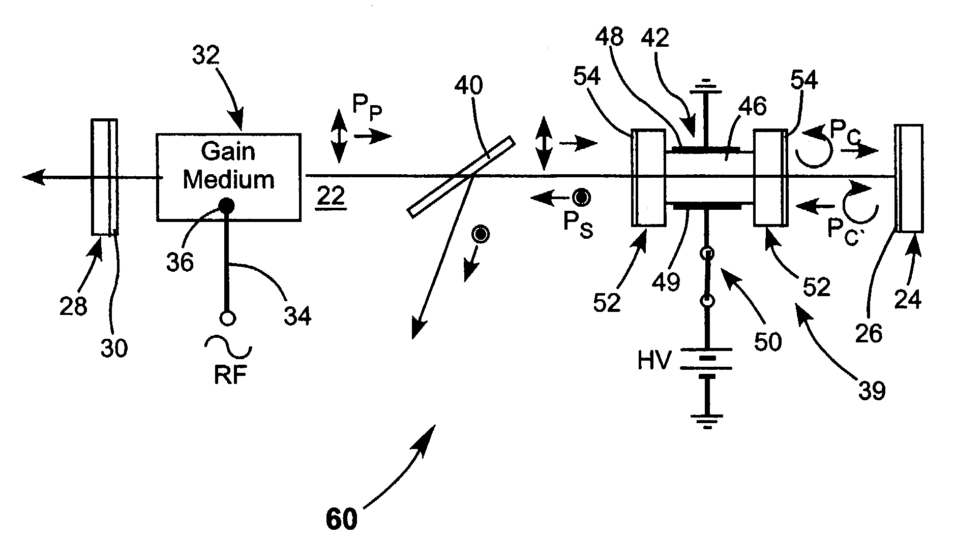
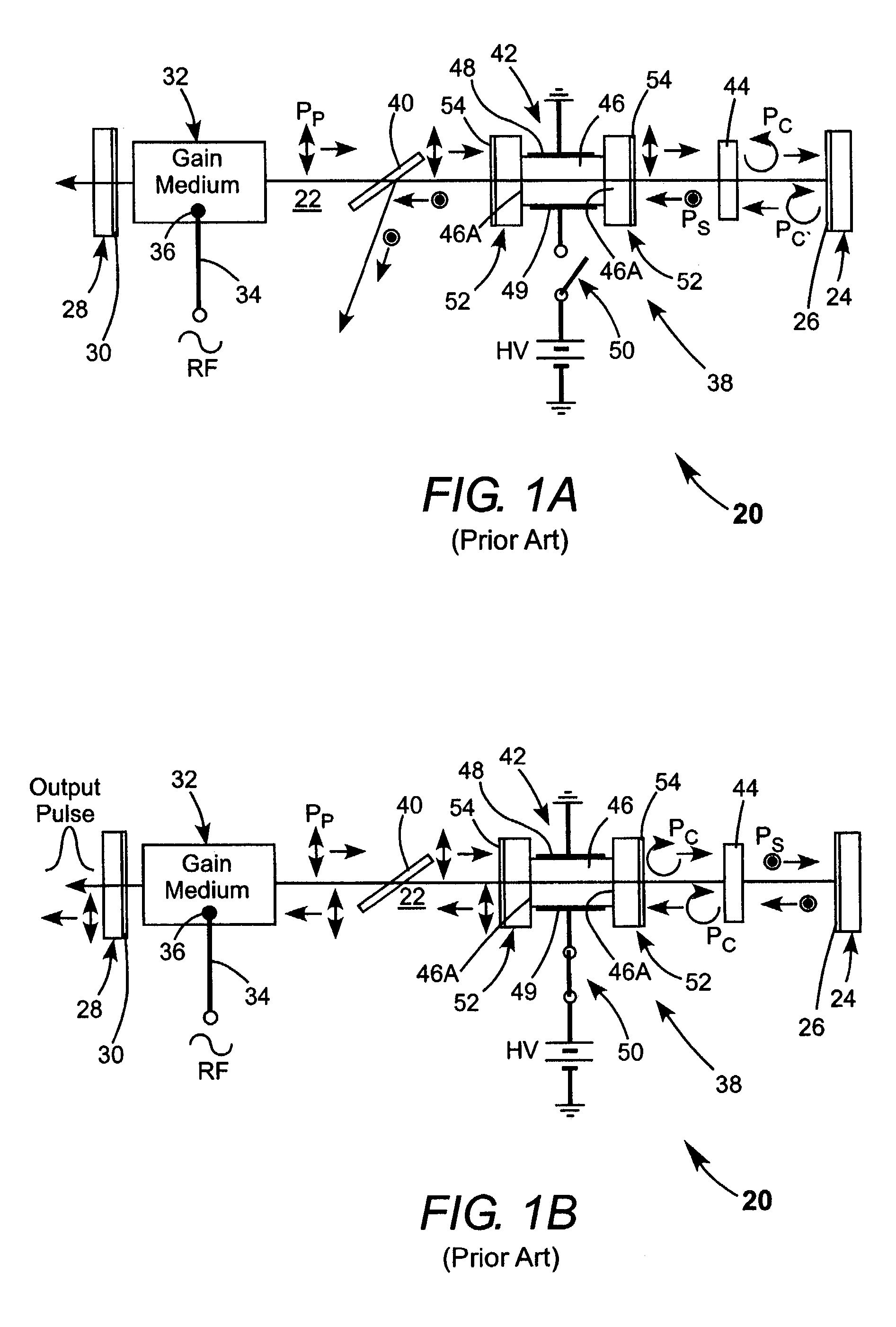
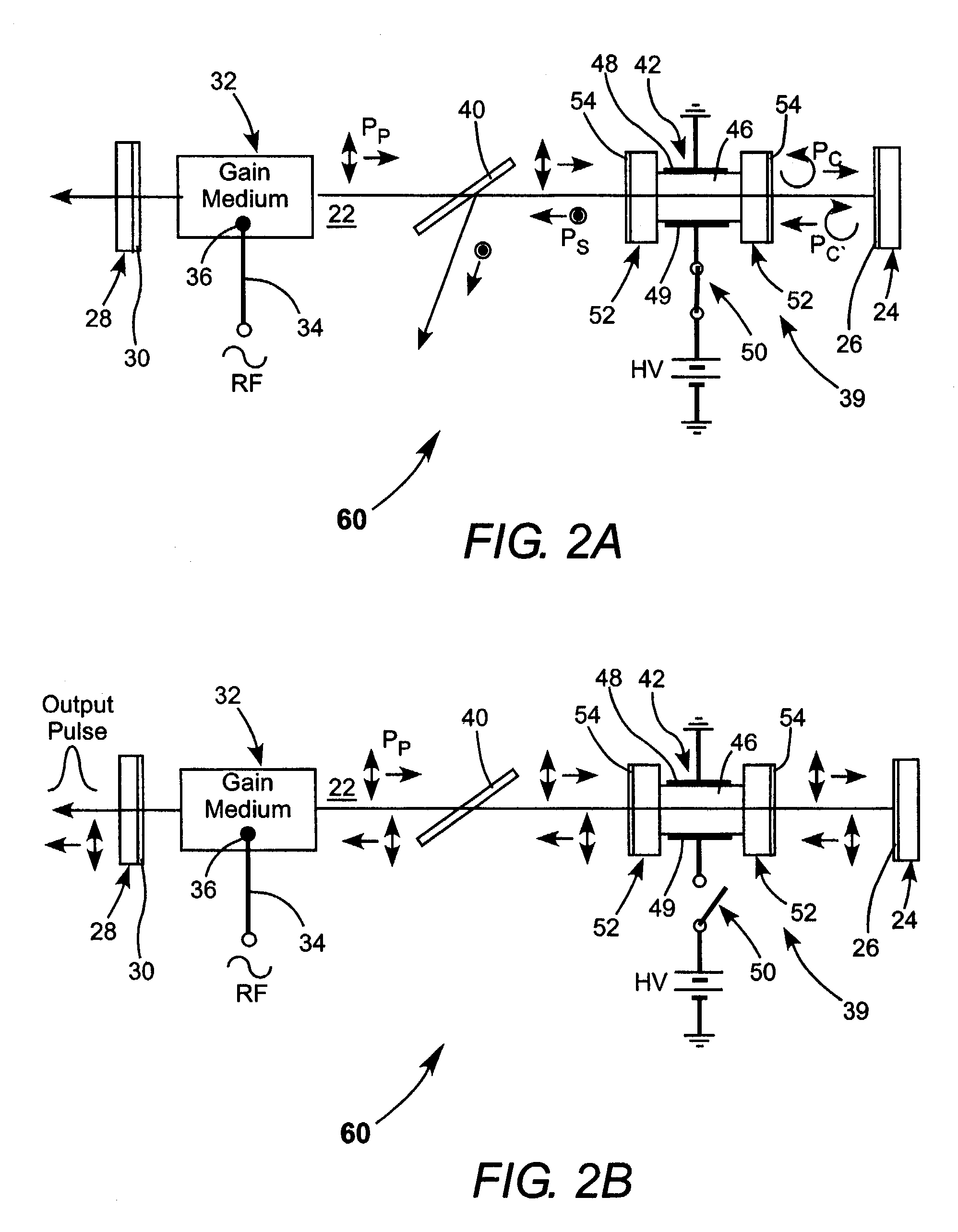
[0037]Turning now to the drawings, wherein like components are designated by like reference numerals, FIGS. 2A and 2B schematically illustrate one preferred embodiment 60 of a pulsed Q-switched laser in accordance with the present invention. Components of laser 60 are similar to those of laser 20 of FIG. 1, with an exception that laser Q-switch arrangement does not include a polarization rotator (quarter-wave phase retarder) 44. This is usually the component most susceptible to optical damage, as discussed above. In the absence of a quarter-wave phase retarder, if switch 50 is open and no voltage is applied to crystal 46 (see FIG. 2B), plane-polarized radiation PP from energized gain-medium 32 can circulate freely in resonator 22.

[0038]When switch 50 is closed (see FIG. 2A) crystal 46 acts as a quarter-wave phase retarder. Plane-polarized radiation PP from gain-medium 32 passes through crystal 46 and is converted to circularly polarized radiation PC. Circularly polarized radiation P...


PUM


Abstract

An electro-optical switch includes an optical assembly arranged to transmit laser-radiation. The optical assembly comprises an active optical crystal. On one of two opposite surfaces of the crystal is an optical window formed from a material having a refractive index lower than the material of the crystal. Heat deposited, as a result of transmission of the laser-radiation, at the surface of the crystal in contact with the widow is transferred to the window, thereby reducing the potential for optical damage to the crystal surface. The window is sufficiently thick that it has an odd integer multiple of quarter-wavelengths optical thickness at a wavelength about equal to a wavelength of the laser-radiation, thereby behaving as an antireflection device for the crystal at that wavelength. In one embodiment of the optical assembly, the active optical crystal is a cadmium telluride crystal and the window is formed from cesium bromide.

Description

TECHNICAL FIELD OF THE INVENTION[0001]The present invention relates generally to Q-switched pulsed lasers. It relates in particular to a Q-switched pulsed carbon dioxide (CO2) laser including a Q-switching arrangement configured to reduce optical damage to components thereof.DISCUSSION OF BACKGROUND ART[0002]Q-Switched pulsed waveguide CO2 lasers are commonly used in material processing operations. Many of these operation require laser-radiation pulses delivered by the lasers to have high peak power, for example about 25 Kilowatts (KW) or greater, with peak instantaneous power intensity of several Megawatts per square centimeter (MW / cm2).[0003]Such a high peak-power intensity can rapidly cause damage to optical components inserted within the laser cavity, in particular to those components configured to perform the Q-switching function. A consequence of this is that laser operational time may be limited to between 100 to 1000 hours before one or more components need to be replaced. A...

Claims


Application Information

Patent Timeline
Patent Type & Authority Patents(United States)
IPC IPC(8): G02B6/26G02B6/00H01S3/034H01S3/106H01S3/115H01S3/223
CPCH01S3/2232H01S3/115H01S3/0346H01S3/09702H01S3/106
Inventor SEGUIN, VERNONNEWMAN, LEONAUSTIN, R. RUSSELDEMARIA, ANTHONY
Owner COHERENT INC
Why Eureka
Try Eureka