Mine and collision protection for passenger vehicle

a passenger vehicle and collision protection technology, applied in the direction of shields, roofs, pedestrian/occupant safety arrangements, etc., can solve the problems of vehicle damage and beyond repair, and achieve the effects of preventing fracture penetration, high strain-rate dependence and hardening, and preventing structural damag

Active Publication Date: 2006-10-03
THE UNITED STATES OF AMERICA AS REPRESENTED BY THE SECRETARY OF THE NAVY
View PDF28 Cites 103 Cited by
  • Summary
  • Abstract
  • Description
  • Claims
  • Application Information

AI Technical Summary

Benefits of technology

[0006]In view of the foregoing, it is an object of the present invention to provide an improved methodology for structurally enhancing wheeled vehicles for protecting passengers from death or serious bodily injury when the vehicles encounter explosive and / or mechanical impacts.
[0007]Other objects of the present invention are to provide such a methodology that is characterized by lower weight and lower cost as compared with conventional methodologies for accomplishing similar types of protection through structural enhancement.
[0008]The present invention represents a lighter, more affordable, more effective way of developing the needed force protection for wheeled vehicles. The present invention was primarily motivated by the need to afford better mine and crash protection to military personnel when riding in susceptible vehicles such as high mobility multipurpose wheeled vehicles (HMMWVs). Typically, inventive practice is not directed at preventing damage to the vehicle; indeed, under usual destructive circumstances a vehicle will incur significant damage, frequently beyond repair, despite inventive practice. Rather, what is normally the primary purpose of the present invention is to protect the occupant or occupants of the vehicle.
[0015]Typical practice provides for use of an elastomeric material that is highly elastic or highly viscoelastic, e.g., characterized by a strain-to-failure of at least 100%, more typically at least 300% to 400% or greater. The present inventors style their elastomeric layer (which contributes to the mine and crash protection of the passenger or passengers) an “explosion resistant coating,” or “ERC.” The ERC material can be practically any elastomer, polymeric or non-polymeric, such as polyurea (a mixture of polyurethane and urea), polyurethane, or rubber. According to typical inventive practice, the inventive ERC has high strain-rate dependence and hardening characteristics to provide shock wave interaction, energy absorption, and prevention of fracture penetration under extreme loads such as mine explosion. Inventive principles are also applicable for crashworthiness purposes to prevent structural damage and reduce acceleration effects on the vehicle's occupants. Regardless of the source of the extreme loading, inventive practice succeeds in avoiding or minimizing injury and fatality.
[0016]The present invention's layered configuration provides protection against blasts and collisions at significantly lower weight and cost than does the existing technology. Because of the reduced weight associated with the inventive elastomer (ERC), the present invention's double-layered combination (one elastomeric layer, one non-elastomeric layer) can be added to a military vehicle without changing the mission capability of the vehicle. Further, the ERC can be applied via casting in place, spraying, or bonding a separate cured piece of elastomer. Because of the varied techniques and procedures at the practitioner's disposal for installation of the ERC, the ERC can be added to areas of vehicles that do not lend themselves to addition of other types of protective materials.

Problems solved by technology

Typically, inventive practice is not directed at preventing damage to the vehicle; indeed, under usual destructive circumstances a vehicle will incur significant damage, frequently beyond repair, despite inventive practice.

Method used


Image

  • Mine and collision protection for passenger vehicle
  • Mine and collision protection for passenger vehicle
  • Mine and collision protection for passenger vehicle

Examples


Embodiment Construction

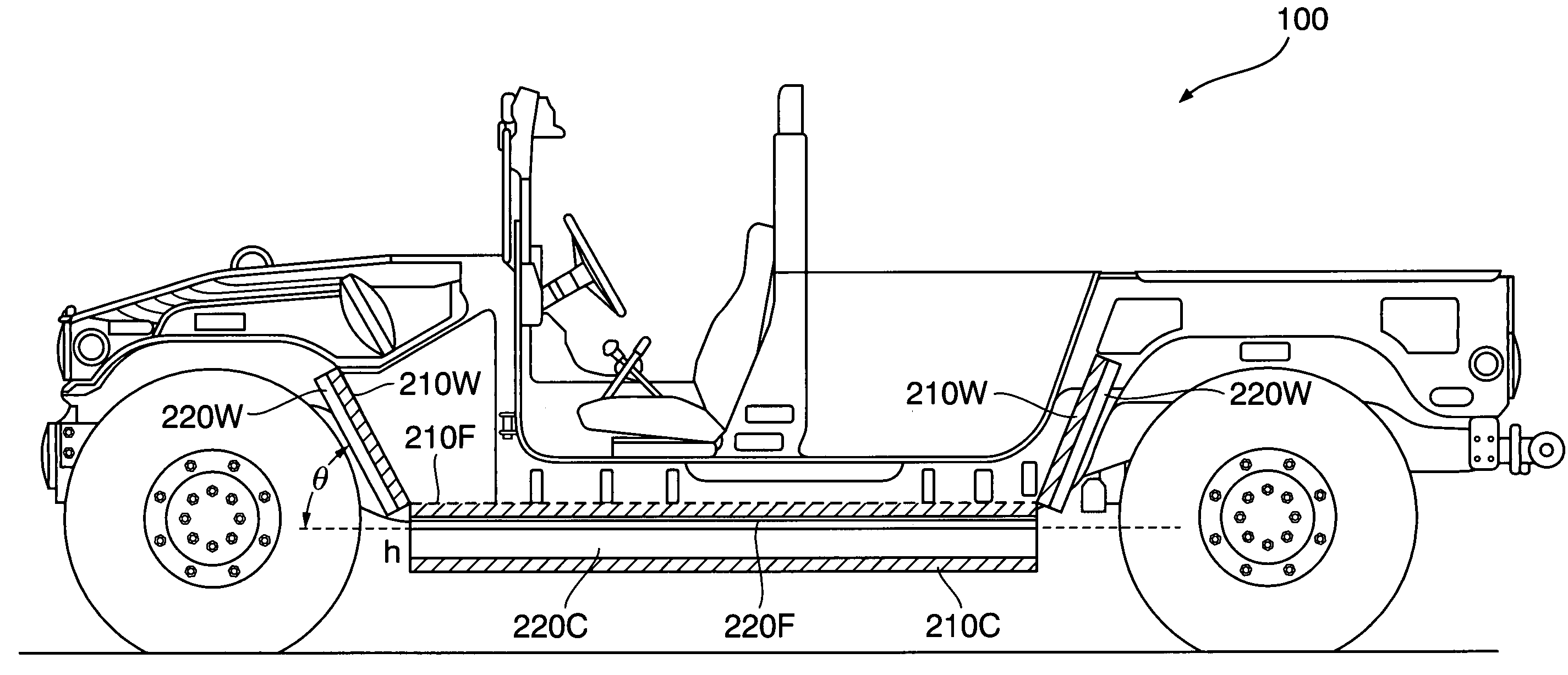
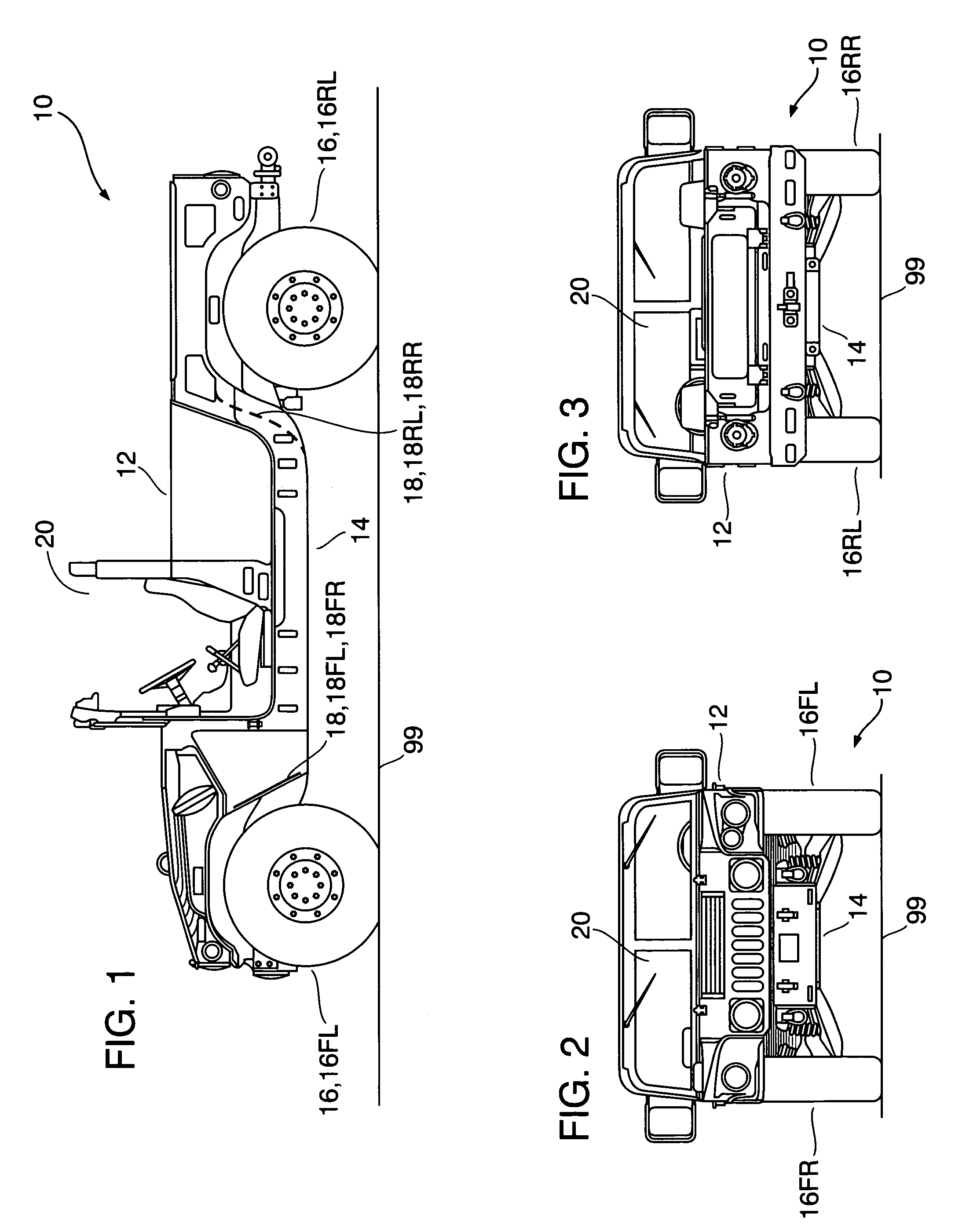
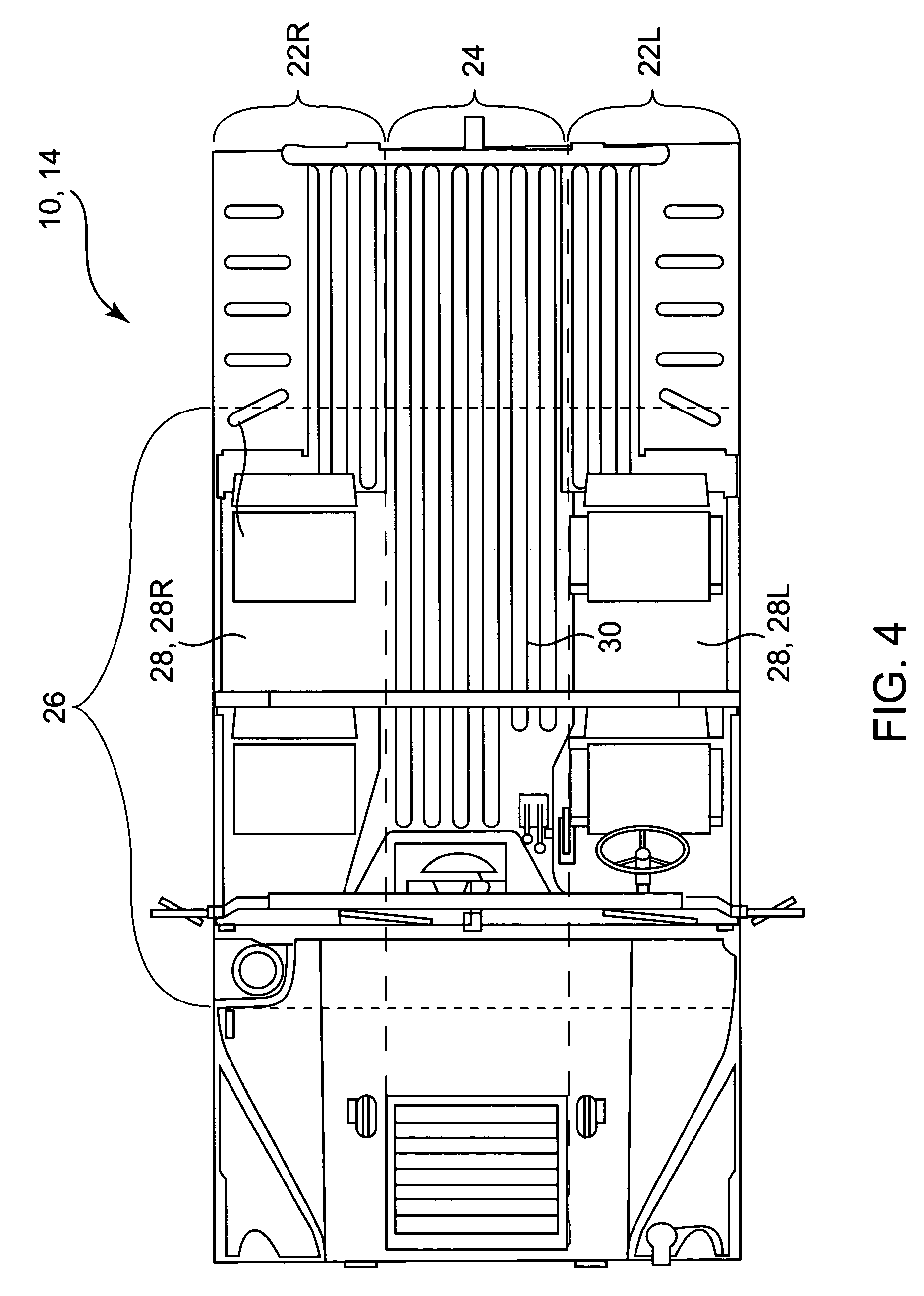
[0027]Referring now to FIG. 1 through FIG. 4, high mobility multipurpose wheeled vehicle (HMMWV) 10 is a typical military passenger vehicle that is suitable for protective amplification in accordance with the present invention. The HMMWV 10 shown in FIG. 1 through FIG. 4 is a standard such vehicle that is not inventively enhanced. Vehicle 10 includes a body 12, an undercarriage 14, four wheels (tires) 16, and four wheel wells 18. Body 12 and undercarriage 14 are distanced above ground 99 by the wheels 16 and their associated axles.

[0028]Front left wheel 16FL and front right wheel 16FR share the front axle; rear left wheel 16FL and rear right wheel 16RR share the rear axle. Each wheel well 18 corresponds to a wheel 16. That is, front left wheel well 18FL is adjacent wheel 16FL; front right wheel well 18FR is adjacent wheel 16FR; rear left wheel well 18RL is adjacent wheel 16RL; rear right wheel well 18RR is adjacent wheel 16RR. Each wheel well 18 is a wall-like or bulkhead-like struc...


PUM


Abstract

Many military land vehicles are not designed to withstand extreme forces concomitant exploding mines. A vehicle's capacity to protect its occupants is inventively enhanced by structurally augmenting the vehicle, in lower structural portions closely related to the vehicle's cabin, with both elastomeric and rigid (non-elastomeric) materials. An elastomeric layer and a rigid layer (typically embodied as a metal or composite sheet or plate) are added to the vehicle in each of seven locations, viz., the four wheel wells (left-front, right-front, left-rear, right-rear), the two floorboards (left and right), and the intervening underside area. At each wheel well and floorboard location, the elastomer is sandwiched between the vehicle's existing rigid structure and the rigid member so as to form a tri-layer material system. At the intervening underside location, an elastomer-coated rigid member is attached with the elastomer face-down. The seven material systems are energy-dissipative and impact-deflective both locally and globally.

Description

STATEMENT OF GOVERNMENT INTEREST[0001]The invention described herein may be manufactured and used by or for the Government of the United States of America for governmental purposes without payment of any royalties thereon or therefor.BACKGROUND OF THE INVENTION[0002]The present invention relates to wheeled transportation vehicles, more particularly to methods and devices for protecting passengers of such vehicles from harm associated with deleterious events such as mine explosions and severe collisions.[0003]It is desirable to protect passengers of a motor vehicle from death or serious bodily injury that they may incur when their motor vehicle encounters highly destructive forces such as associated with explosions and collisions. Passenger protection has been a concern for both military and commercial vehicles, the former being particular vulnerable when riding over land mines or otherwise being subjected to explosive forces.[0004]Some current approaches for affording mine and / or cr...

Claims


Application Information

Patent Timeline
Patent Type & Authority Patents(United States)
IPC IPC(8): B60R21/00F41H7/00
CPCB60R19/00F41H7/042B60R2021/0013
Inventor BARSOUM, ROSHDY GEORGE S.PETERSON, RODNEY O.OWEN, DAVID P.JONES, WAYNE C.JOHNSON, DAVID E.
Owner THE UNITED STATES OF AMERICA AS REPRESENTED BY THE SECRETARY OF THE NAVY
Why Eureka
Try Eureka