Method and apparatus for safety protocol verification, control and management

a technology of safety protocol and control and management, applied in the field of safety verification systems, can solve the problems of human error or oversight affecting the execution of the three-step protection protocol, and oversight could be deadly

Active Publication Date: 2014-01-14
EHRLER ERIC +1
View PDF20 Cites 10 Cited by
  • Summary
  • Abstract
  • Description
  • Claims
  • Application Information

AI Technical Summary

Benefits of technology

[0016]This invention could be highly desirable to railroad personnel as a means of further protecting railroad employees from serious injury or death. In addition, the present invention has applicability to a variety of other industrial settings wherein the actions of multiple individuals are used to control dangerous equipment. Examples of this could include the lockout tagout system typically used by utilities to de-energize power lines and power equipment.

Problems solved by technology

Although these steps or conditions are well known and mandatory, it is possible that human error or oversight could interfere with the execution of the three-step protection protocol.
In such a situation, the oversight could be deadly.

Method used


Image

  • Method and apparatus for safety protocol verification, control and management
  • Method and apparatus for safety protocol verification, control and management
  • Method and apparatus for safety protocol verification, control and management

Examples


Embodiment Construction

[0027]While the invention will be described in connection with certain embodiments, the description should not be construed to limit the invention to these embodiments. On the contrary, the intent is to cover all alternatives, modifications and equivalents as included within the spirit and scope of the invention. Various changes may be made to the function and arrangement of the elements described herein, without changing the scope of the invention being disclosed. It should be noted that the following description serves to teach at least one instance of how the various elements may be arranged to achieve the stated goals of this invention.

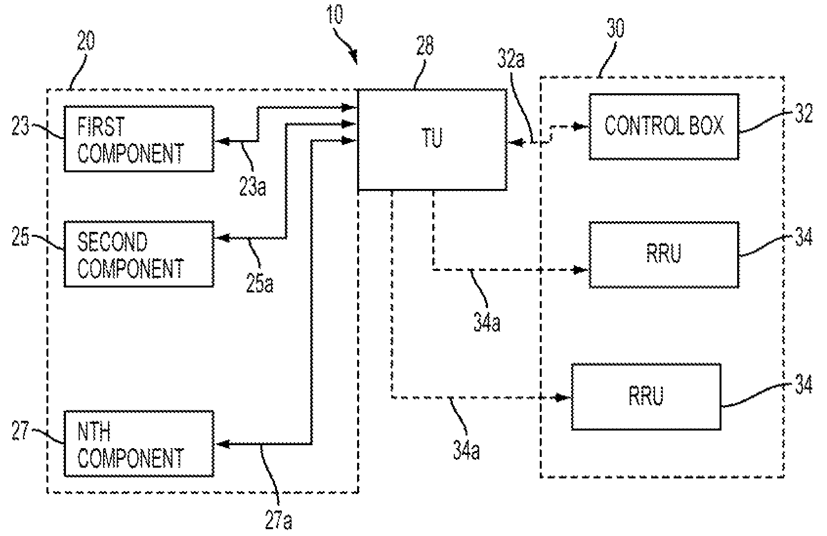
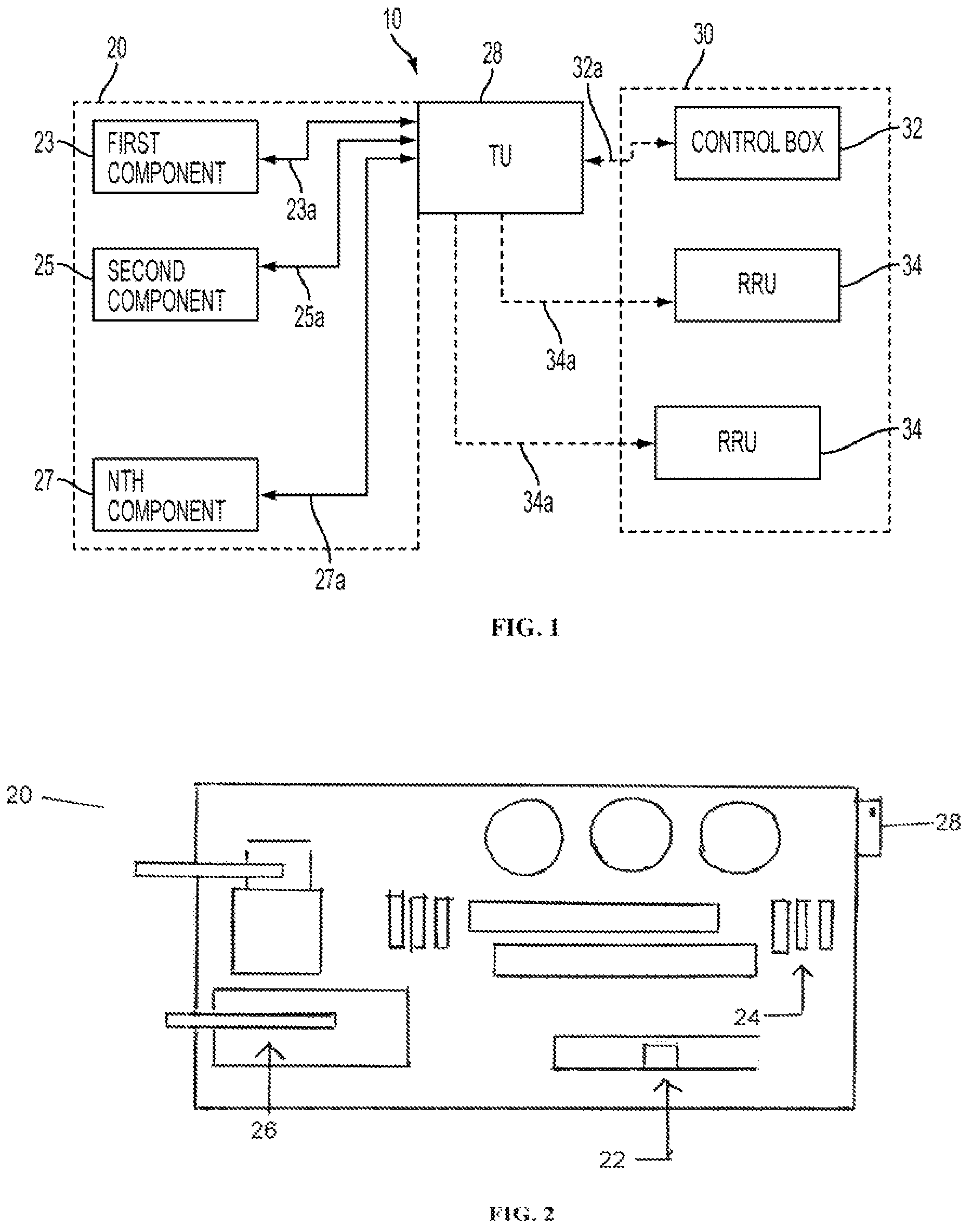
[0028]FIG. 1 is a block diagram for one embodiment of a safety system 10, showing its electronic circuitry. Equipment 20 is shown with an attached Transceiver or Transmitter Unit (“TU”) 28. The equipment itself may comprise of a plurality of interlinked components. Each such component may be in one of two states—either engaged or disengaged. The f...


PUM


Abstract

The present invention is an apparatus and a method for a safety verification system, or a safety verification management system. At railroads or construction sites, equipment, such as a piece of heavy machinery, or a locomotive engine, must be subjected to a safety protocol before authorized personnel are allowed to approach the equipment. It is essential to have independent, automatic confirmation that the safety protocol has been successfully completed. In railroad systems, a Three Step Protection Mode is often used to place a locomotive engine in safe mode. One embodiment of the present invention provides an independent, automatic verification that this safety protocol has been successfully completed and sends an audible, visual, audiovisual, or vibratory signal to remote personnel. Another embodiment tracks the relative positions of personnel and locomotives, and generates a warning when personnel are proximate to an equipment that is not in safe mode.

Description

BACKGROUND OF THE INVENTION[0001](a) Technical Field of the Invention[0002]This invention generally relates to the field of safety verification systems, and in particular relates to an electronic signaling system that monitors safety protocols associated with an equipment, and alerts remote personnel upon the satisfactory completion of such protocols. This enables the alerted personnel to approach the equipment safely.[0003](b) Description of the Relevant Art[0004]A considerable number of patents relate generally to safety protocols and safety verification mechanisms.[0005]In U.S. Pat. No. 4,937,795, Motegi, et al. disclose an access alarm method for the purpose of protecting personnel as they are working on vehicles. As stated in the patent, this could specifically include railroad locomotives, as well as aircraft and a number of other vehicles. With the primary embodiment disclosed by Motegi, the alarm consists of an ultrasonic signal transmitted by a receiver on the vehicle to in...

Claims


Application Information

Patent Timeline
Patent Type & Authority Patents(United States)
IPC IPC(8): G08G1/00H04B3/36G05D1/00B61L5/20
CPCG06F19/00B61L23/00B61L25/021B61L23/06
Inventor EHRLER, ERICJOHNSON, MARK
Owner EHRLER ERIC
Why Eureka
Try Eureka