Eureka AIR delivers breakthrough ideas for toughest innovation challenges, trusted by R&D personnel around the world.

Hang tag and method of applying hang tag to an elongated object

a technology of hanging tags and elongated objects, applied in the field of tags, can solve the problems of largely unsuccessful increase in safety of warnings included with packaging, particularly susceptible to injury or death of electric cord sets, and low surface energy materials, so as to avoid serious injuries and deaths, and low cost

Inactive Publication Date: 2005-01-25
WS PACKAGING GROUP
View PDF13 Cites 6 Cited by
  • Summary
  • Abstract
  • Description
  • Claims
  • Application Information

AI Technical Summary

Benefits of technology

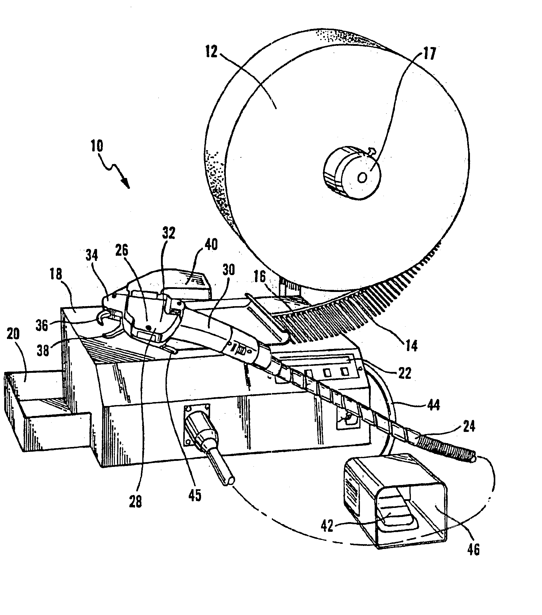
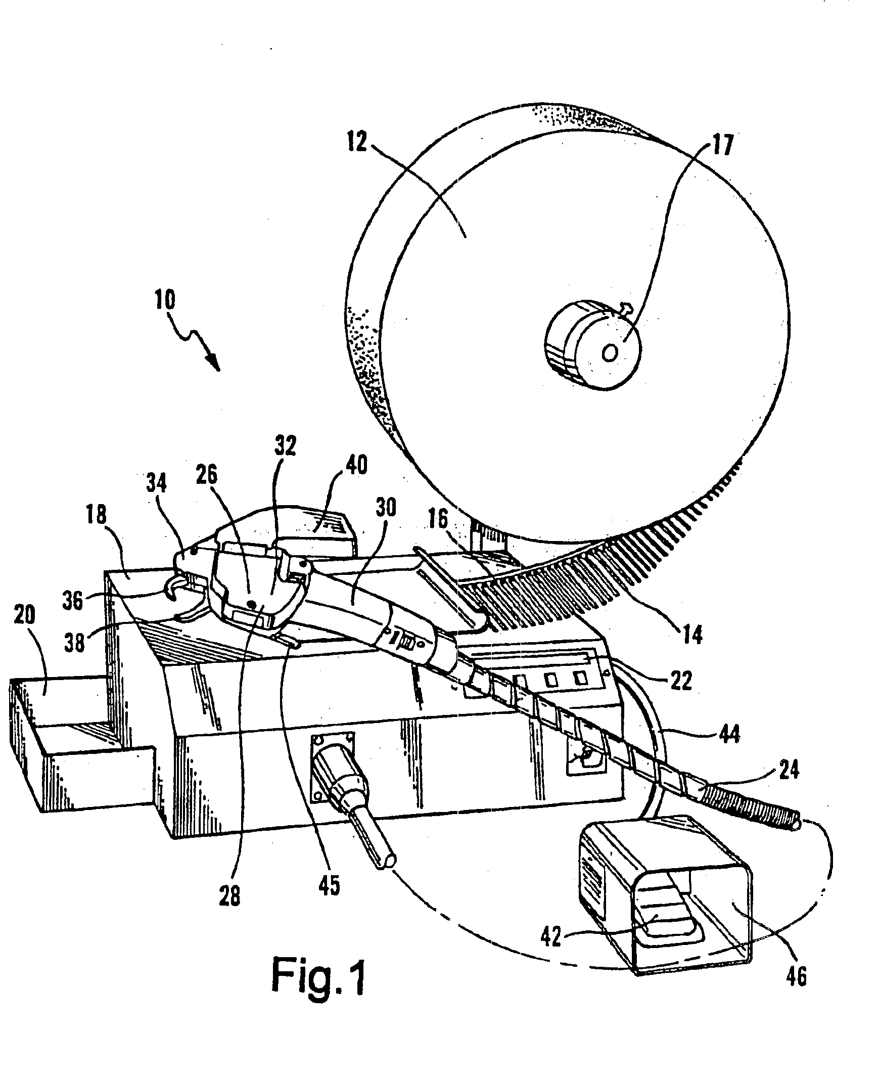
Advantageously, pursuant to the present invention, by applying a hang tag to an elongated object, particularly electrical cords, long-term cautionary information can be provided to consumers thereby educating consumers as to how to avoid serious injuries and deaths attributed to electrical shock. Significantly, the present invention not only permits automatic application of a hang tag, but the applied hang tag has also passed tests which suggest that it is able to withstand significant long-term “wear and tear” in use, while remaining legible and staying fastened to the electrical cord to which the hang tag is originally attached. In addition, the inventive method, apparatus, and hang tag accommodate adherence to a diverse range of electrical cord insulation sizes and types, which are typically low surface energy materials. Furthermore, the method, apparatus, and hang tag of the present invention are relatively inexpensive and easy to apply rapidly, thereby increasing the volume of production per unit of time.

Problems solved by technology

Electrical cord sets are particularly susceptible to causing injury or death due to electrical shock.
For example, if a male end of a cord set is inserted into a power source, a dangerous situation exists unless a female end of the cord set is also appropriately connected, for example, to a power supply cord which is hard-wired into a device, such as, for example, a computer.
Unfortunately, the warnings included with the packaging were largely unsuccessful in increasing safety because consumers ordinarily discard the packaging prior to initial use of the electrical cord.
As such, any communications provided with the packaging were ill-suited for reminding consumers of potential dangers upon subsequent use.
The problem was exacerbated when the communications were provided on an inside surface of the packaging because the warnings often would go entirely unnoticed by the consumer.
However, because electrical cords generally have outer insulation jackets that are composed of materials which have a relatively low surface energy (such as various rubbers and thermoplastics), securely attaching the source of the cautionary information has proven to be difficult.
However, the use of adhesive labels as the source of cautionary information has not been fully satisfactory for all electrical cord applications.
To date, it is believed that no affordable or marketable adhesive label has been able to satisfy UL 817 with respect to the fuel oil submersion test.
However, a significant drawback with using hang tags is that they previously have been limited to manual application with respect to electrical cords.
Manually applying hang tags to electrical cords is cumbersome and results in increased labor costs and increased production time.
Previous attempts to automatically apply the hang tags to the electrical cords have not met with success.
For example, it has proven difficult to provide a hang tag that can be automatically applied and which also retains sufficient structural integrity to withstand long term “wear and tear” (e.g., to pass UL 817 Standard for cord sets and power supply cords, including those requiring oil resistance).

Method used


Image

  • Hang tag and method of applying hang tag to an elongated object
  • Hang tag and method of applying hang tag to an elongated object
  • Hang tag and method of applying hang tag to an elongated object

Examples


example 1

This example illustrates the durability and resistance to “wear and tear” of hang tags according to the invention.

In particular, three hang tags (i.e., Tag #1, Tag #2, and Tag #3) were prepared. Each hang tag was formed from a C2S Valeron Film (7.5 mil). Each hang tag was prepared with a generally rectangular slot defined therein, having radiused edges. The slot in each of the hang tags had dimensions of 0.375 inches by 1.375 inches. Tag #1 had a slot with a minimum distance of 0.20 inches from any edge of the hang tag. Tag #2 had a slot with a minimum distance of 0.156 inches from any edge of the hang tag. Tag #3 had a slot with a minimum distance of 0.15 inches from any edge of the hang tag. Each tag was attached and tensioned to an electrical cord using a cable tie (Panduit PLT1M-XMR).

Each tag was subjected to all of the tests required for passing UL Standard 817 (see, e.g., U.S. Pat. No. 5,658,648). All three hang tags (#1-#3) passed all of the UL 817 tests, including 48 hours s...


PUM

PropertyMeasurementUnit
weightaaaaaaaaaa
thicknessaaaaaaaaaa
thicknessaaaaaaaaaa

Abstract

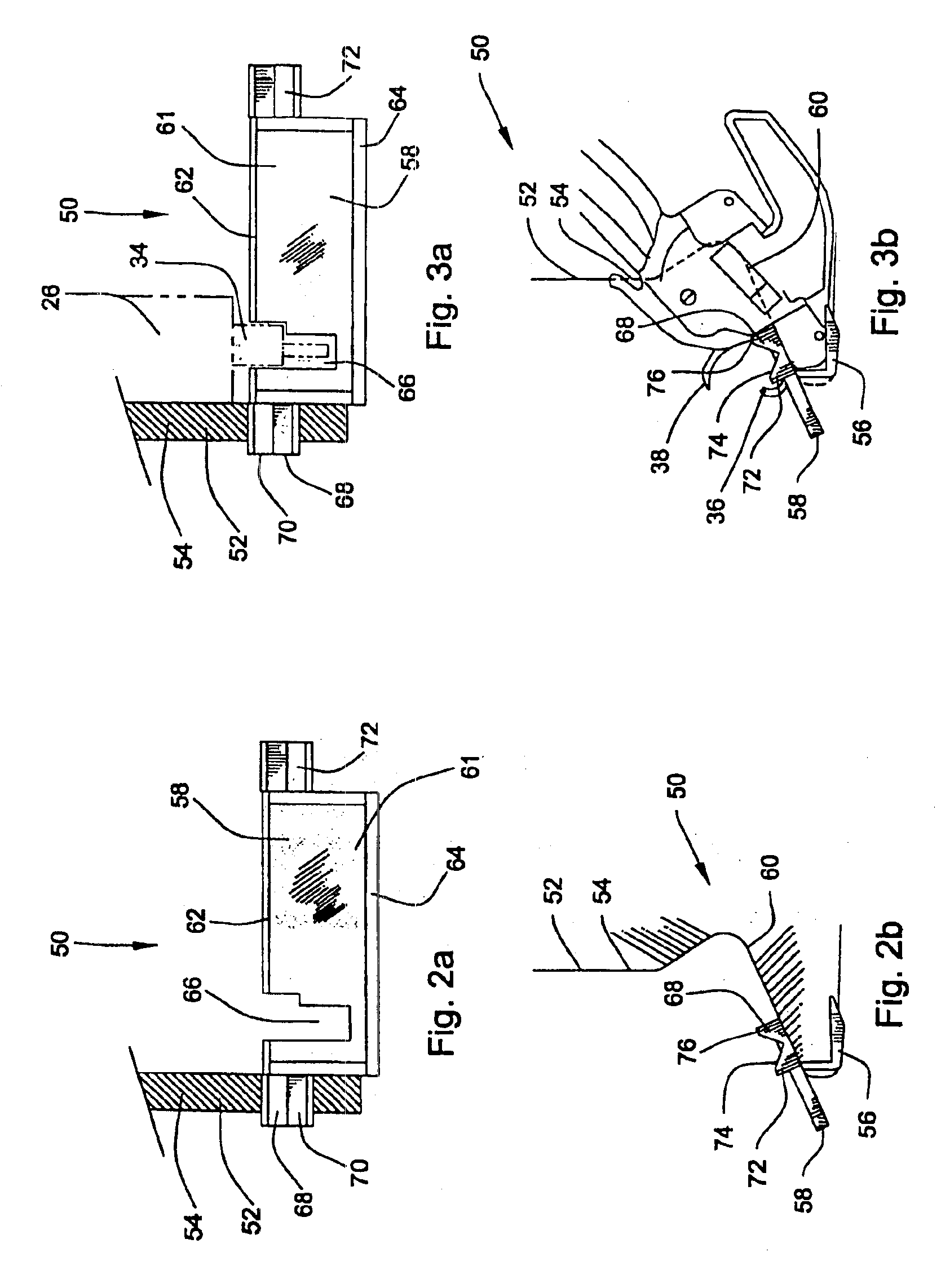
A hang tag is disclosed. The hang tag has first and second surfaces, which are preferably planar. A slot is defined between the first and second surfaces. Desirably, the slot extends at least about 0.25 inches in one direction and at least about 1 inch in another direction. Also disclosed is a method and an apparatus for automatically applying a hang tag to an elongated object (e.g., an electrical cord such as a cord set), with a machine that is suitable for applying a securement strap to an object. The method includes providing a hang tag having a slot therein. The hang tag is aligned with the machine so that when the securement strap is ejected from the machine, it passes through the slot, forms a loop around the elongated object, and is tensioned around the object. As such, the securement strap serves to attach the hang tag to the elongated object in a stationary manner.

Description

TECHNICAL FIELD OF THE INVENTIONThe present invention pertains generally to tags. More particularly, the present invention relates to hang tags and methods of applying hang tags to elongated objects, as might be particularly useful for application to electrical cord sets.BACKGROUND OF THE INVENTIONIn order to prevent consumers from suffering serious or even fatal injuries caused by electrical shock, manufacturers of electrical cords, such as cord sets and power supply cords, have sought to caution consumers of the various dangers that exist when electrical cords are not used properly. Electrical cord sets are particularly susceptible to causing injury or death due to electrical shock. For example, if a male end of a cord set is inserted into a power source, a dangerous situation exists unless a female end of the cord set is also appropriately connected, for example, to a power supply cord which is hard-wired into a device, such as, for example, a computer.Historically, manufacturers...

Claims


Application Information

Patent Timeline
Patent Type & Authority Patents(United States)
IPC IPC(8): B65C3/02B65C3/00B65C7/00
CPCB65C7/00B65C3/02
Inventor DOERR, CHRISTOPHERHEPP, AMIELVOSS, ROBERT
Owner WS PACKAGING GROUP
Why Eureka
Eureka Blog
Learn More