Illumination systems and methods of use

a technology of illumination system and light-emitting diode, which is applied in the direction of semiconductor devices for light sources, lighting and heating apparatus, lighting support devices, etc., can solve the problem that leds do not produce enough light to illuminate another surface, and achieve high efficiency and shock resistance.

Inactive Publication Date: 2006-10-03
MCCULLOUGH WAYNE +2
View PDF12 Cites 71 Cited by
  • Summary
  • Abstract
  • Description
  • Claims
  • Application Information

AI Technical Summary

Benefits of technology

[0011]Unlike conventional incandescent light bulbs / lamps, LEDs are highly efficient, in that most of the power consumed by an LED is converted into visible light. The efficiency of LEDs allows them to be incorporated into compact, streamlined designs with smaller and lighter batteries or other power sources. Further, LEDs are highly shock resistant and therefore provide significant advantages over incandescent and fluorescent bulbs, rendering LEDs ideal for critical applications, such as pilot-mounted aircraft cockpit illumination. LEDs possess operating lifetimes from 200,000 hours to 1,000,000 hours, as compared to the typical 1,000 to 2,000 hours for incandescent lamps. Finally, LEDs avoid the transience and inductance problems associated with incandescent lamps, allowing LEDs to be incorporated into various structures using simple circuitry.

Problems solved by technology

Until recently, LEDs did not produce enough light to illuminate another surface.

Method used


Image

  • Illumination systems and methods of use
  • Illumination systems and methods of use
  • Illumination systems and methods of use

Examples


Embodiment Construction

[0027]For the purposes of promoting an understanding of the principles of the invention, reference will now be made to the embodiment illustrated in the drawings and specific language will be used to describe the same. It will nevertheless be understood that no limitation of the scope of the invention is thereby intended, and alterations and modifications in the illustrated device, and further applications of the principles of the invention as illustrated therein, are herein contemplated as would normally occur to one skilled in the art to which the invention relates.

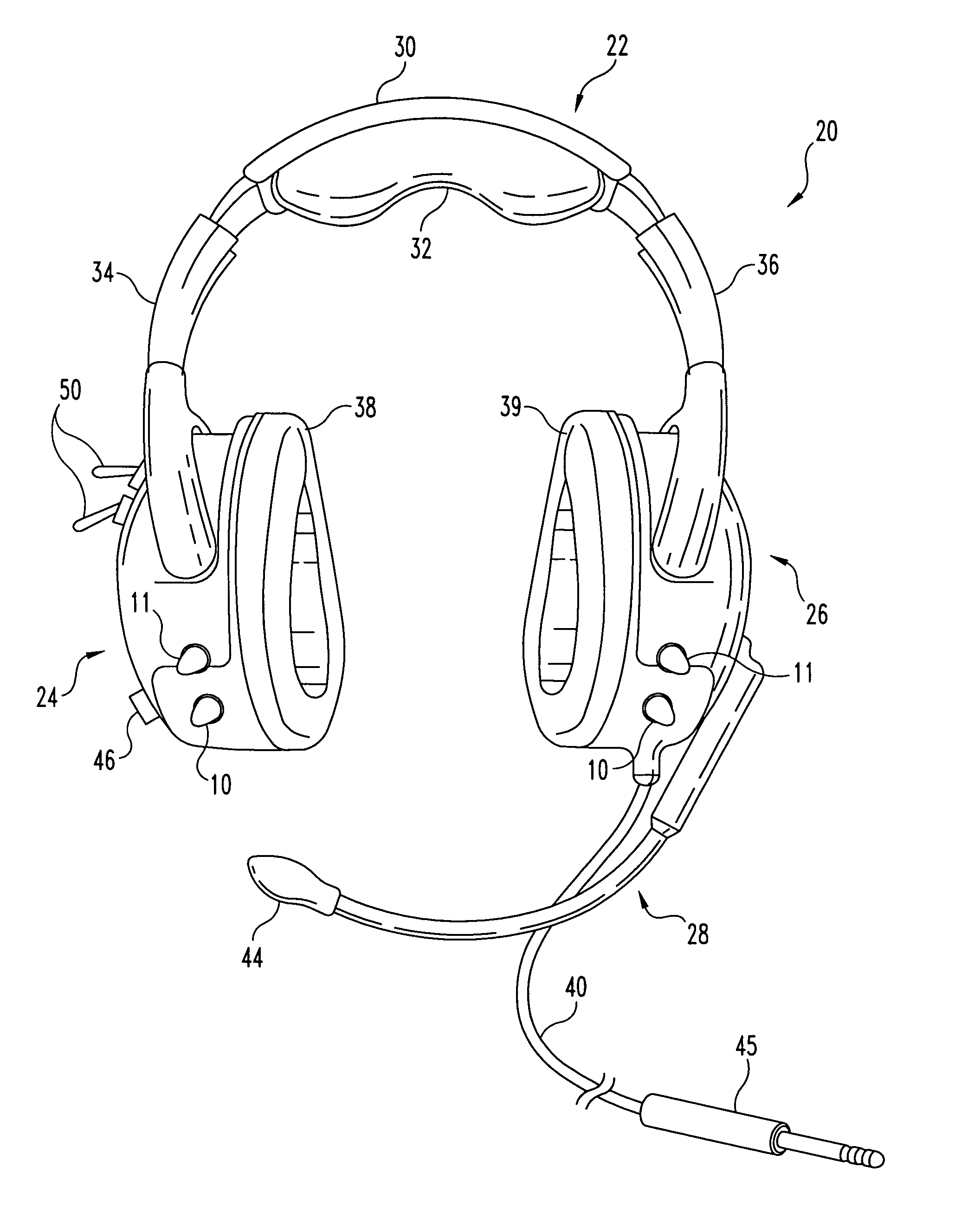
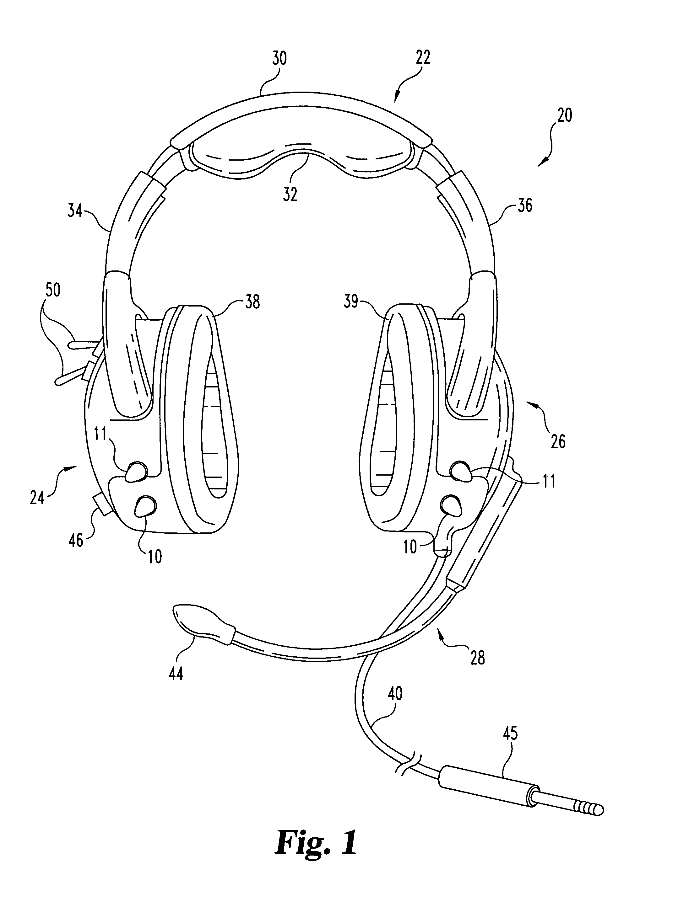
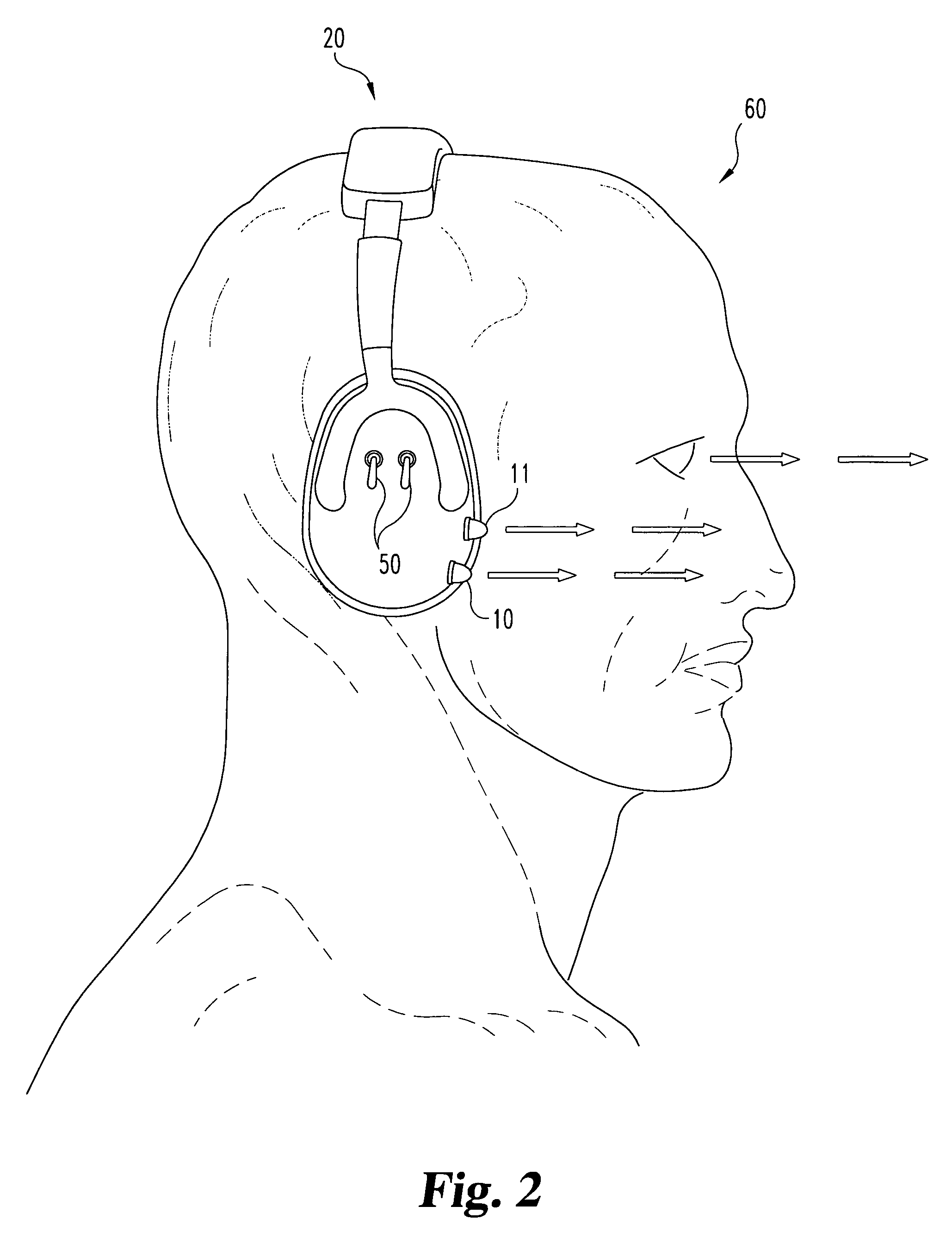
[0028]The present invention is directed to hands-free illumination devices using LEDs, and is described below primarily in the context of illumination devices used in conjunction with headgear, in particular aircraft headsets. However, other embodiments covered by the invention simply substitute for aircraft headsets any other body-mounted object, including headgear such as: spectacle-like frames, including safety glass...


PUM


Abstract

The present invention provides a high-intensity LED as a light source for use in hands-free illumination devices. In one embodiment, one or more high-intensity LEDs are incorporated in, or added to, headgear, such as an aircraft headset. The LEDs may be powered by a battery, an external power source, or both. Also provided is a kit and method of installation for retrofitting existing headgear with LEDs.

Description

FIELD OF THE INVENTION[0001]The invention is directed generally to portable illumination systems, and more particularly to a hands-free / body-mounted light emitting diode (“LED”) as a light source.BACKGROUND OF THE INVENTION[0002]Conventional portable illumination systems, such as flashlights, include an incandescent light bulb and conventional drycell batteries enclosed in a housing typically constructed of a body section and a head section. Though portable, illumination systems of this type are often bulky and cumbersome, and thus often are not carried on the person. This presents a problem when the need for illumination arises unexpectedly, such as during a power failure at night, and no portable illumination system is readily available. The problem is exacerbated when, for instance, the person does not have a hand available to search for, aim and operate a conventional flashlight.[0003]There have been some variations on portable, hands-free illumination systems. Underground coal ...

Claims


Application Information

Patent Timeline
Patent Type & Authority Patents(United States)
IPC IPC(8): F21V21/084H04R1/10H04R31/00F21V33/00H04M1/05H04M1/60
CPCF21V33/0056H04M1/05F21Y2101/02H04M1/6033Y10S362/80F21Y2115/10
Inventor MCCULLOUGH, WAYNEMAGEE, BRYANLYKINS, MATTHEW
Owner MCCULLOUGH WAYNE
Why Eureka
Try Eureka