
Strain-relief device for a plug-in connection in communications and data systems

a technology of strain relief device and plug-in connection, which is applied in the direction of coupling device connection, coupling protective earth/shielding arrangement, electrical apparatus, etc., can solve the problems of relatively complex design and inconvenient adjustment of cable conductors, and achieve the effect of improving contact quality

Inactive Publication Date: 2006-10-03
COMMSCOPE TECH LLC
View PDF13 Cites 25 Cited by
  • Summary
  • Abstract
  • Description
  • Claims
  • Application Information

AI Technical Summary

Benefits of technology

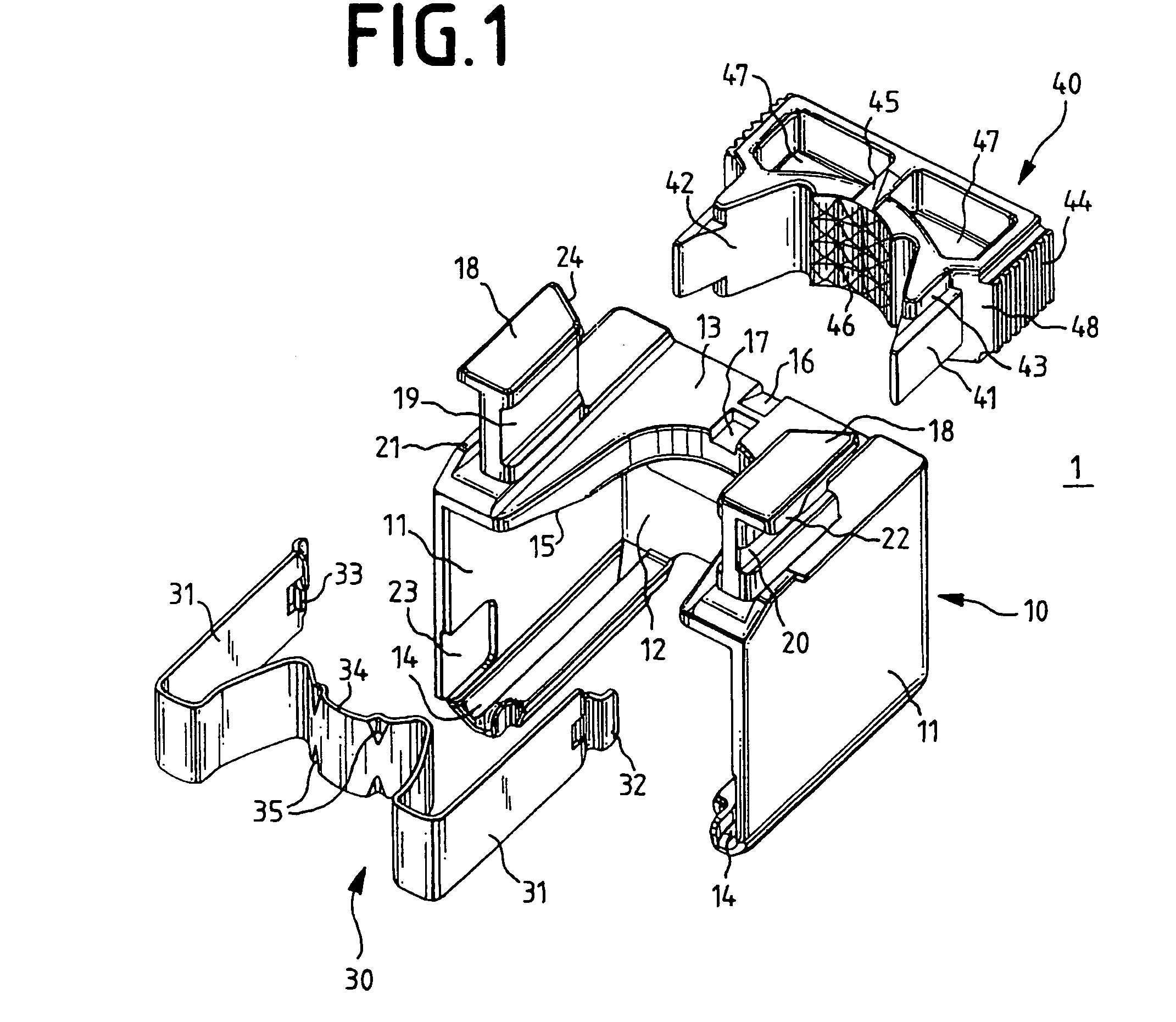
[0010]For this purpose, the strain relief device has a base part for holding at least part of the plug connector and a cable which can be connected to the plug connector, with the base part being designed with first latching means, and closure means, with the closure means being designed with second latching means which form a latching connection with the first latching means on the base part, in which the closure means are in the form of a spring comprising two limbs which can be pushed along a guide onto the base part, with the base part being designed with at least one support point for the spring, and the spring being designed such that an opposing force, which is produced by the cable moves the second latching means, which are arranged on the limbs, toward the first latching means on the base part. There is thus no need for any sprung elements on the base part, so that the base part need not necessarily be produced from plastic but, for example, can also be produced as a die casting which, apart from increased strength, also has considerable cost advantages.
[0014]In one preferred embodiment, bends are arranged at the free ends of the limbs of the spring, in order to make it easier to detach the spring from the base part when required.
[0016]In a further preferred embodiment, the head part can be latched as a separate component, in a captive manner, on top of the base part. Designing it as a separate component simplifies manufacture, since there is no need to manufacture any moving parts while, on the other hand, the captive attachment makes it possible to handle the base part and the head part as a single component during use.

Problems solved by technology

The known strain relief devices have the disadvantage that the cable conductors are not aligned in a precisely defined manner with respect to the contacts of a plug connector which is to be connected to the cable.
The known strain relief device has the disadvantage that its design is mechanically relatively complex owing to the moving jaw parts, which means that it must be manufactured from plastic.

Method used


Image

  • Strain-relief device for a plug-in connection in communications and data systems
  • Strain-relief device for a plug-in connection in communications and data systems
  • Strain-relief device for a plug-in connection in communications and data systems

Examples


Embodiment Construction

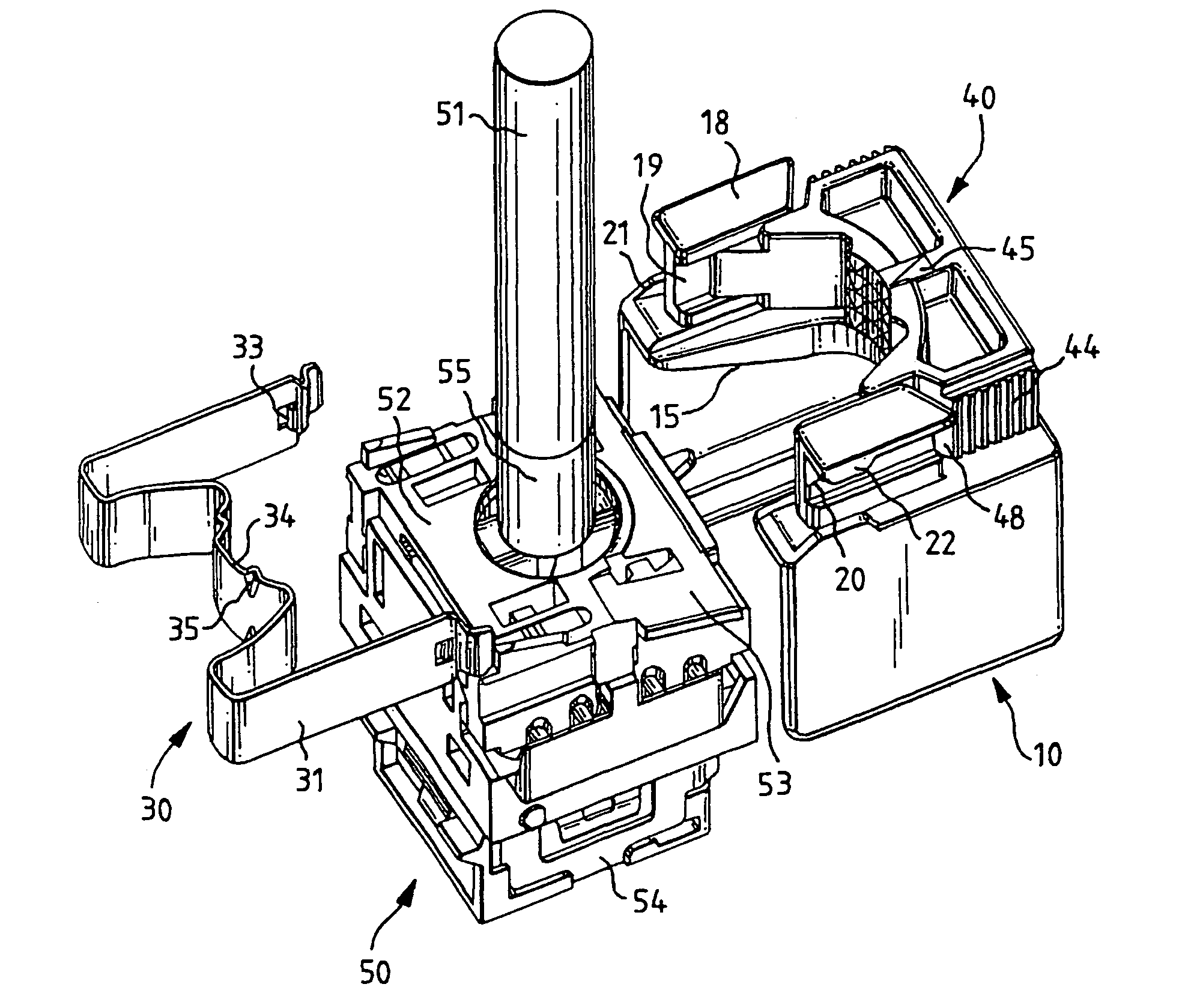
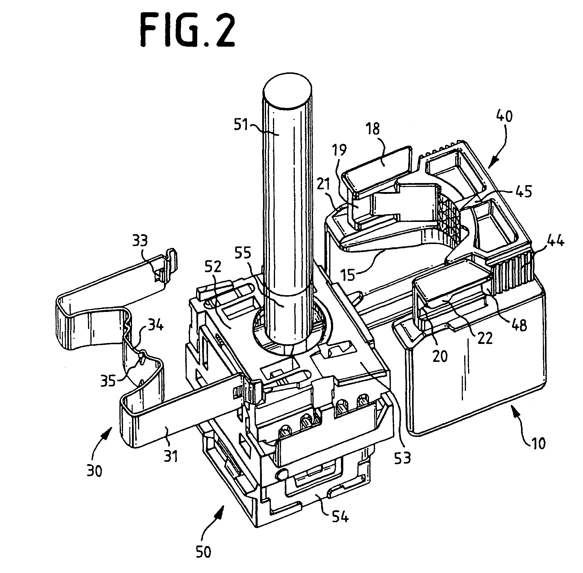
[0025]The strain relief device 1 has a base part 10, closure means 30 and a head part (i.e., latching member) 40. The base part 10 has two side walls 11, a rear wall 12 and an upper part 13. Guide edges 14 are arranged on the lower face of the side walls 11 and are at right angles to the rear wall 12. Guide edges 15, which run obliquely toward the rear, run on the upper face of the side walls 11 and on the lower face of the upper part 13. In the front region, the upper part 13 has a rounded cutout for holding a cable, which is not shown. On the side facing the rear wall 12, the upper part 13 has an incline 16 which runs inward and upward, and behind which a depression 17 is located. Two guide elements 18 are arranged in the front, side region of the upper part 13. Each guide element 18 firstly forms a guide 19 on the inside, and a guide 20 on the outside. In the region of the guide 20, the side wall 11 is raised somewhat above the upper part 13 in the front region, and forms a first...


PUM


Abstract

The invention relates to a strain relief device (1) for a plug connect for communications and data technology, comprising a base part (10) for holding at least part of the plug connector, and a cable (51) which can be connected to the plug connector, with the base part (10) being designed with first latching means, and closure means (30), with the closure means (30) being designed with second latching means which form a latching connection with the first latching means on the base part (10), wherein the closure means (30) are in the form of a spring comprising two limbs (31) which can be pushed along a guide (20) onto the base part (10), with the base part (10) being designed with at least one support point (21) for the closure means (30), and the closure means (30) being designed such that an opposing force, which is produced by the cable (51) moves the second latching means, which are arranged on the limbs (31), toward the first latching means on the base part (10).

Description

REFERENCE TO PRIORITY APPLICATION[0001]This application is a national stage application of PCT / EP02 / 09023, filed Aug. 12, 2002, which is the international application of Serial No. DE 101 46 119.4, filed Sep. 19, 2001, and which applications are incorporated herein by reference. A claim of priority to both, to the extent appropriate, is made.FIELD OF THE INVENTION[0002]The invention relates to a strain relief device for a plug connector for communications and data technology.BACKGROUND OF THE INVENTION[0003]Strain relief devices for cables for communications and data technology have been known in widely differing embodiments for a long time.[0004]DE 40 09 297 C2 discloses an apparatus for attaching at least one cable to the racks or housings of telecommunications devices, having at least two toothed rods which are arranged on the rack part, in which case at least one cable is inserted between the toothed rods and can be secured by means of a spring element which can be clamped betwe...

Claims


Application Information

Patent Timeline
Patent Type & Authority Patents(United States)
IPC IPC(8): H01R13/58H01R13/658
CPCH01R13/5808H01R13/5812H01R13/65802H01R13/6583H01R13/58
Inventor NAD, FERENC
Owner COMMSCOPE TECH LLC
Learn More