Drive axle assembly for hybrid electric vehicle

a hybrid electric vehicle and drive axle technology, applied in the direction of electric propulsion mounting, transportation and packaging, gearing, etc., can solve the problems of oversized motors for most operational conditions, difficult to package relatively large electric motors in certain vehicle configurations, and not being the most effective for the operation requirements of such vehicles. , to achieve the effect of minimizing the redesign of the vehicle structur

Active Publication Date: 2006-10-03
ARVINMERITOR TECH
View PDF17 Cites 31 Cited by
  • Summary
  • Abstract
  • Description
  • Claims
  • Application Information

AI Technical Summary

Benefits of technology

[0006]The electric motor and the engine drive the gear reduction through a planetary gear assembly. The planetary gear assembly reduces the speed from an electric motor shaft to a pinion gear within the gear reduction. The input yoke drives an input shaft which is directly engaged with a planet carrier of the planetary gear assembly such that the input shaft directly drives the pinion gear without speed reduction. That is, in a disclosed embodiment there is no reduction between the input yoke and pinion gear.
[0007]In another embodiment, an axle assembly is powered only by the electric motor to provide a relatively lighter duty axle assembly for a vehicle configuration that does not require significant modification to the axle assembly.
[0008]The present invention therefore provides a lightweight and compact electric motor driven axle configuration, which permits electric hybrid power train configurations that utilize relatively conventional axle and suspension components to minimize redesign of the vehicle structure.

Problems solved by technology

Electric motors for such applications are typically sized to meet both torque and speed requirements, which may not be the most effective for the operational requirements of such vehicles.
This may result in an oversized motor for most operational conditions.
Moreover, the relatively large electric motors may be difficult to package in certain vehicle configurations.
Conversely, utilizing a multiple of relatively smaller electric motors may increase complexity.
However, vehicle manufacturers may be reluctant to adapt electric hybrid power trains to existing vehicles due to the expense associated with redesign.
Such redesign often requires relatively expensive and complicated chassis modifications to mount the additional electric components such as motors and gearboxes.

Method used


Image

  • Drive axle assembly for hybrid electric vehicle
  • Drive axle assembly for hybrid electric vehicle
  • Drive axle assembly for hybrid electric vehicle

Examples


Embodiment Construction

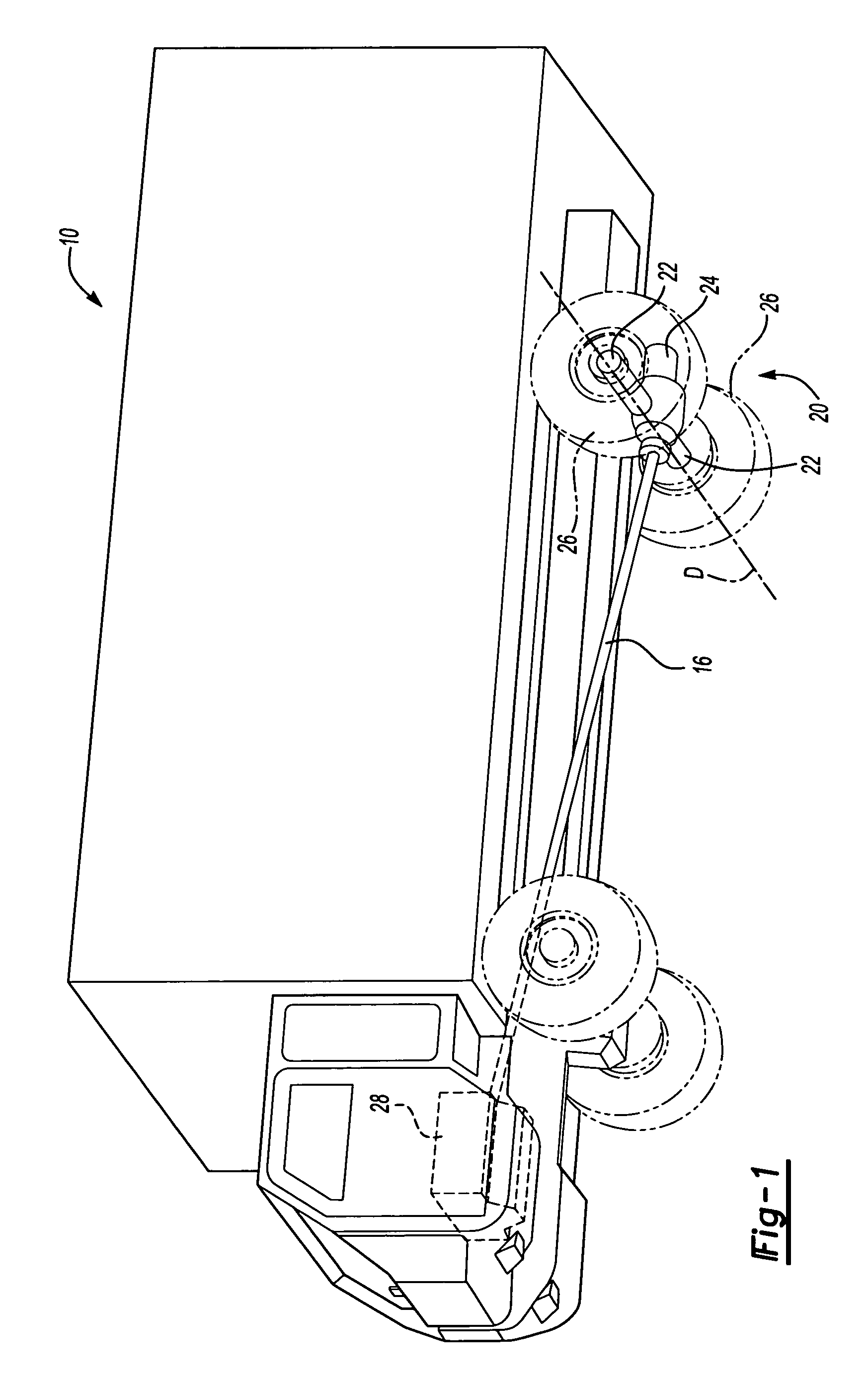
[0015]FIG. 1 illustrates a schematic, partial phantom view of a vehicle 10. It should be understood that although a particular vehicle arrangement is disclosed in the illustrated embodiment, other vehicles will benefit from the present invention.

[0016]An axle assembly 20 is driven by an electric motor 24. An engine 28, such as an internal combustion engine, diesel engine, gas turbine or the like, may additionally be utilized to drive axle assembly 20 as a complement to the electric motor 24. Shaft 16 transmits drive from engine 28 to drive axle assembly 20. Either or both the electric motor 24 and engine 28 are utilized in selective combination in response to particular drive situations. The axle assembly 20 defines an axis of rotation D substantially transverse to shaft 16. The wheel hubs 22 each support one or more wheels 26, which are driven about the axis of rotation D.

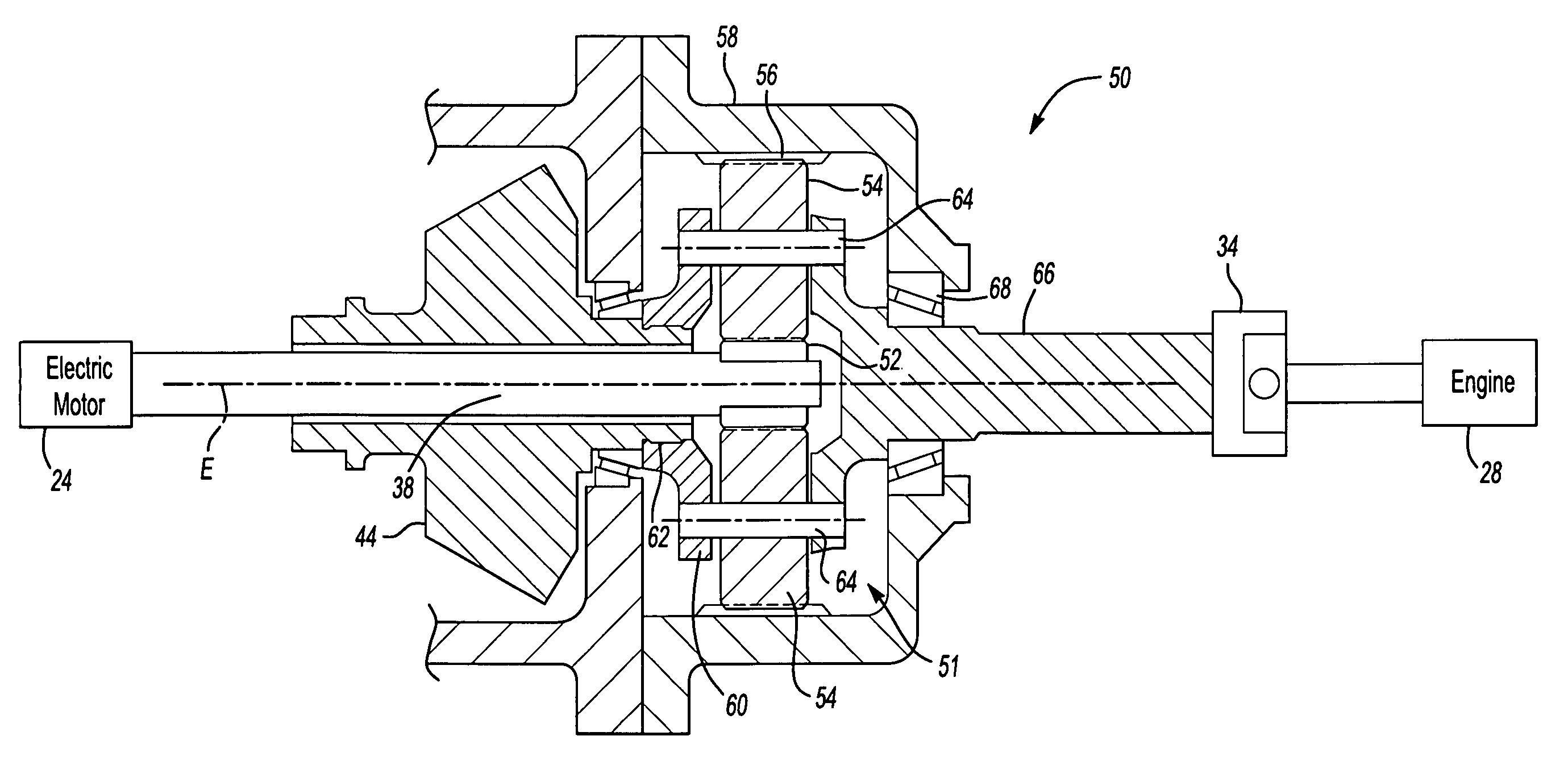
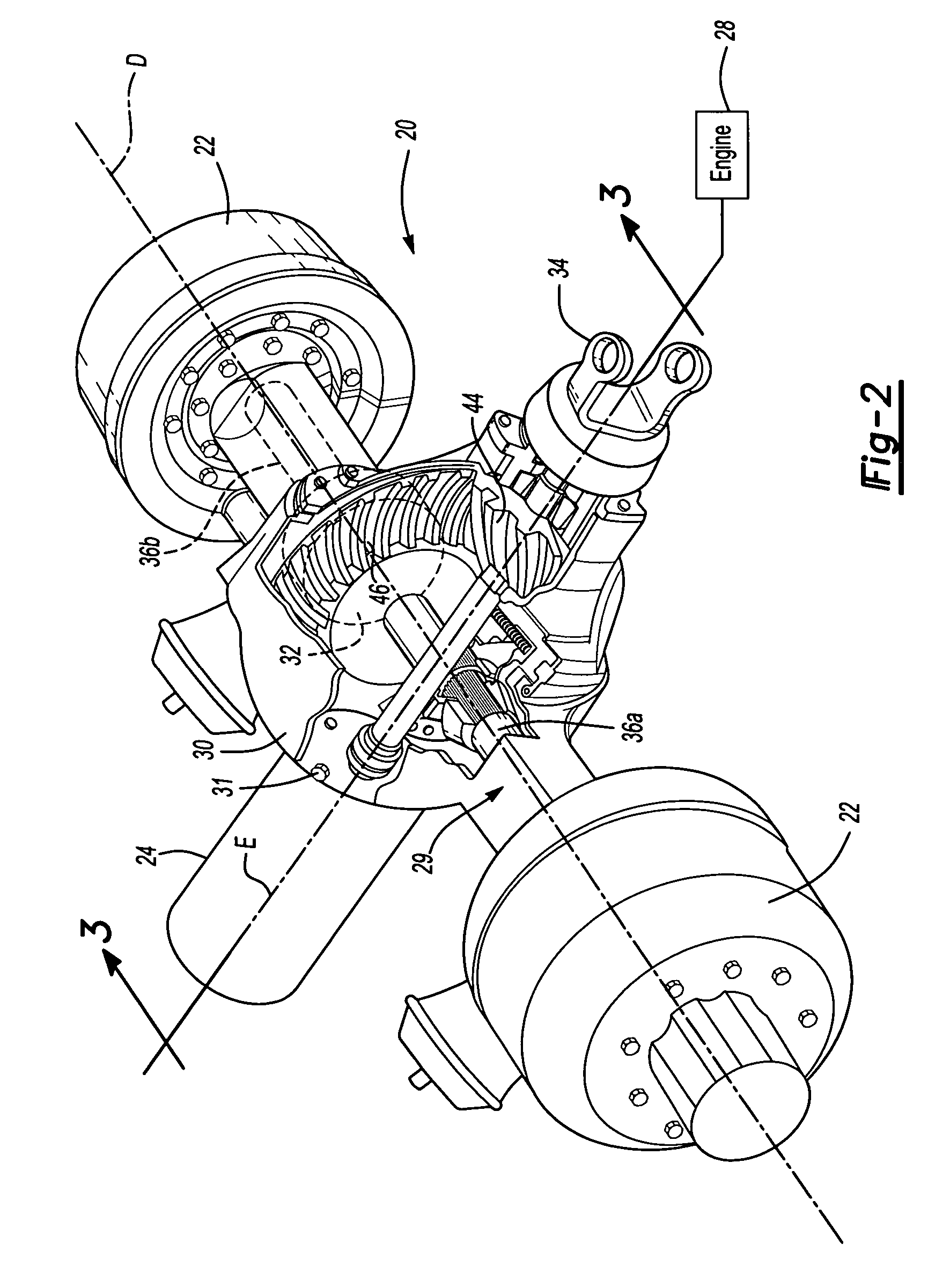
[0017]Referring to FIG. 2, the axle assembly 20 includes an axle housing 29, which supports the wheel hubs 22. ...


PUM


Abstract

An axle assembly mounts an electric motor to a central housing opposite an input yoke that is driven by an engine. The input yoke is mounted along an axis parallel to the electric motor to alternatively or additionally permit the engine to drive a gear reduction within the axle housing through a planetary gear assembly. Another axle assembly is powered by just an electric motor to provide a relatively lighter duty axle assembly for yet another vehicle configuration.

Description

BACKGROUND OF THE INVENTION[0001]The present invention relates to a drive axle assembly including an electric motor, and more particularly to an axle configuration that locates the electric motor in an axle housing opposite from an engine input.[0002]There is an increasing demand for hybrid electric driven and hybrid electric assisted vehicles. Electric motors for such applications are typically sized to meet both torque and speed requirements, which may not be the most effective for the operational requirements of such vehicles. Relatively large electric motors are often utilized to meet the torque requirements. This may result in an oversized motor for most operational conditions. Moreover, the relatively large electric motors may be difficult to package in certain vehicle configurations. Conversely, utilizing a multiple of relatively smaller electric motors may increase complexity.[0003]Electric hybrid power trains offer advantages for both torque and speed requirements. However,...

Claims


Application Information

Patent Timeline
Patent Type & Authority Patents(United States)
IPC IPC(8): F16H3/72B60K1/00F16H37/08F16H48/06
CPCB60K6/365B60K6/40B60K6/48F16H3/724B60Y2200/14Y02T10/6221Y02T10/62
Inventor HOUSE, DEAN M.
Owner ARVINMERITOR TECH
Why Eureka
Try Eureka