
Horizontally stacked hemming press

Active Publication Date: 2011-03-03
HIROTEC AMERICA
View PDF13 Cites 10 Cited by
  • Summary
  • Abstract
  • Description
  • Claims
  • Application Information

AI Technical Summary

Benefits of technology

[0004]The present invention provides a horizontal stack press that may include four dies in the press, and the number of dies can be reduced or expanded from as low as two dies to as high as five or more dies.
[0005]The present horizontal stack press has the following advantages over conventional vertical press arrangements. No gravitational forces move the load in the horizontal orientation. The weight of lifting three and one-half dies (or any plurality of dies) in the vertical position would cause a significant increase in the press drive size necessary to carry the load. The height of a vertical system would cause significant increases in required clearance height if a vertical press could be configured with four dies. Adjustment of the dies would be very dangerous in the vertical position due to the height of the upper dies in the stack from the floor. Maintenance of the top structure of a vertical press would be very difficult due to the height of the press.
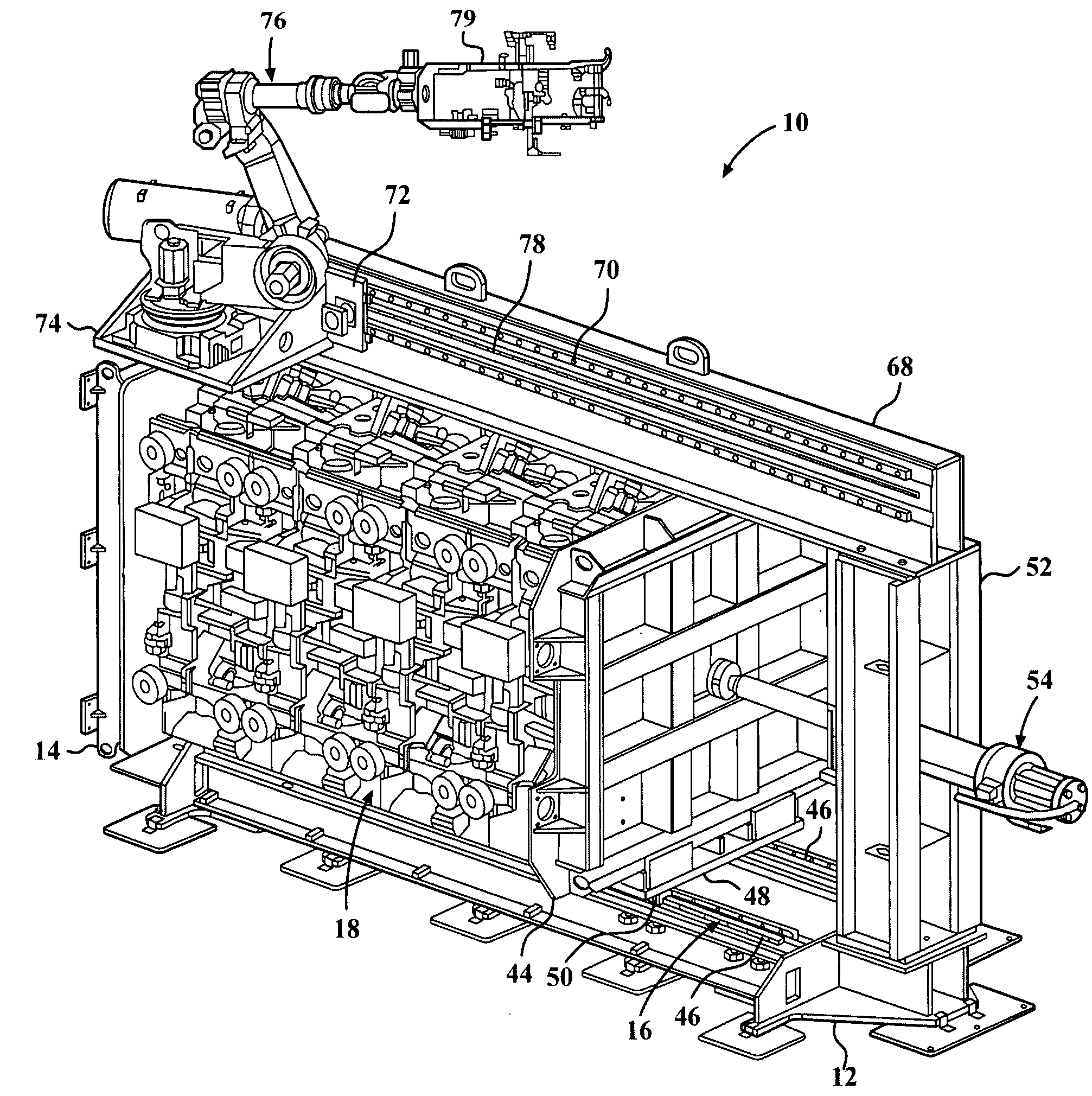
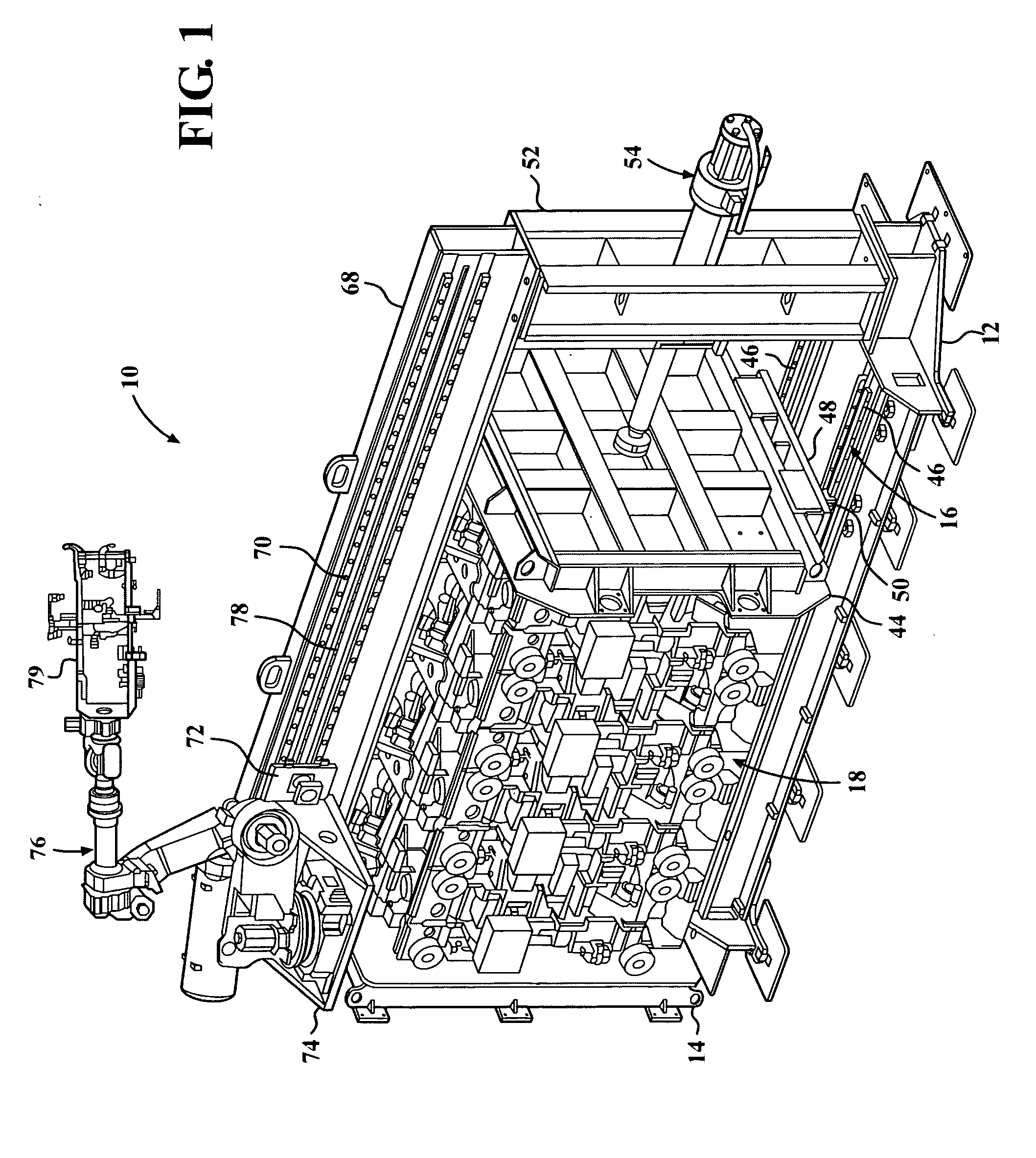
[0006]The present horizontal hemming press arrangement places all the equipment at a reasonable height from the floor. The present horizontal press can be shipped and installed as one integral unit, while a vertical press has to be disassembled for shipping due to height constraints of shipping by truck or similar carrier. The clamping mechanism that locks the die faces together are much lighter duty in the present horizontal press because the clamping mechanism is not subjected to the gravitational load of the dies. Safety lockouts are much lighter in the present horizontal press because of the lack of gravitational forces. The load and unload robot system is built into the top structure of the present horizontal press, saving floor space required for part handling in any traditional closure panel assembly system. This applies to press and die style, table top style and roller hemming configurations.
[0007]The present horizontal press saves up to 75% of the floor space requirements in comparison to conventional press arrangements, thereby decreasing the size of the closure panel production line. The expense, space, and complexity of a die change system are reduced by the present horizontal press. One drive system operates all four (or any plurality of) dies. In contrast, each hemmer of a table top or individual press needs its own drive system.
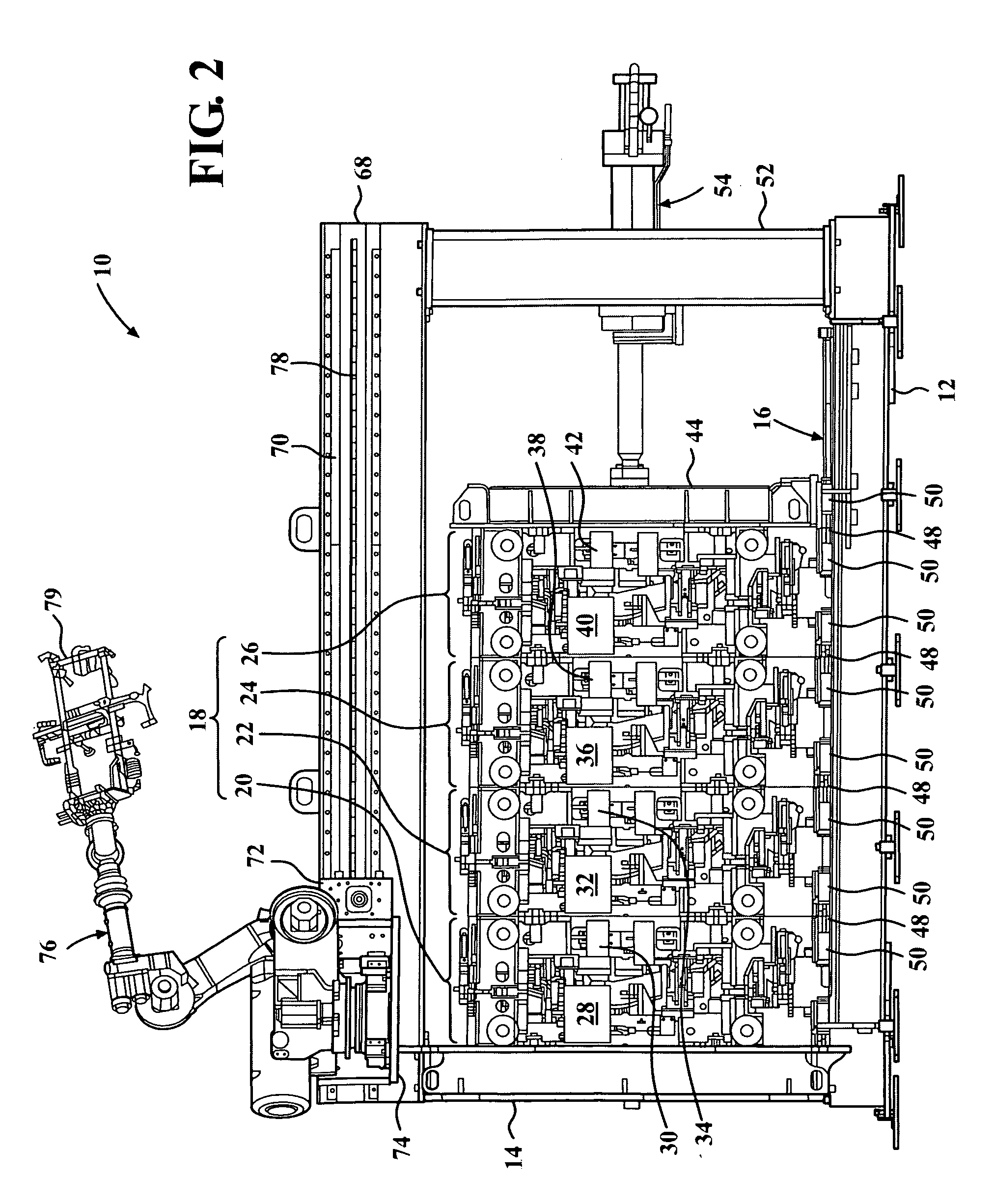
[0012]Each die set may include two or more workpiece clamps that hold a hemming workpiece in a vertical disposition against a mating surface in the die set. Each workpiece clamp may include a clamp arm terminating in a clamp finger for engaging a workpiece. The clamp arm may be pivotable between a closed clamping position and an open receiving position. A pneumatic cylinder may be connected to the clamp arm. The pneumatic cylinder may bias the clamp arm in the closed position and may be capable of moving the clamp arm between the closed and open positions. A stop may limit movement of the clamp arm in the closed position. A cam may be connected to the clamp arm. The cam may be actuated by a cam driver to move the clamp arm from the closed position to the open position.

Problems solved by technology

The weight of lifting three and one-half dies (or any plurality of dies) in the vertical position would cause a significant increase in the press drive size necessary to carry the load.
The height of a vertical system would cause significant increases in required clearance height if a vertical press could be configured with four dies.
Adjustment of the dies would be very dangerous in the vertical position due to the height of the upper dies in the stack from the floor.
Maintenance of the top structure of a vertical press would be very difficult due to the height of the press.

Method used


Image

  • Horizontally stacked hemming press
  • Horizontally stacked hemming press
  • Horizontally stacked hemming press

Examples


Embodiment Construction

[0027]Referring now to the drawings in detail, numeral 10 generally indicates a horizontally stacked hemming press in accordance with the present invention. The horizontal hemming press 10 includes a plurality of cooperably operable hemming die sets horizontally arranged in series, and in contrast to conventional presses the plurality of hemming die sets are horizontally actuated and moved (opened / closed) in a generally horizontal direction. The horizontal hemming press 10 is shorter (and therefore has a reduced height requirement) in comparison to conventional vertical presses. The horizontal hemming press 10 also has a smaller footprint and therefore provides a floor space savings in comparison to using a plurality of presses each having a dedicated die set, to using a plurality of table top hemmers each for a dedicated part / product, and to using a plurality of roller hemming cells each for a dedicated part / product. The horizontal hemming press 10 further provides an energy saving...


PUM

PropertyMeasurementUnit
Pressureaaaaaaaaaa

Abstract

A horizontally stacked hemming press includes a horizontally disposed base. A first vertical support is mounted on the base and disposed generally perpendicular to the base. A linear track is mounted on the base. A horizontally disposed die stack including a plurality of cooperably operable die sets are horizontally arranged in series and moveable along the linear track. Each die set includes a pair of vertically disposed die shoes. A guided press platen is horizontally moveable along the linear track. A second vertical support is mounted on the base distal from the first vertical support and disposed generally perpendicular to the base. A drive mechanism is supported by one of the supports and connected to the press platen for opening and closing the die sets. Actuation of the drive mechanism horizontally moves the press platen and thereby horizontally opens one of the die sets.

Description

CROSS REFERENCE TO RELATED APPLICATION[0001]This application claims the priority of U.S. Provisional Application No. 61 / 237,051 filed Aug. 26, 2009.TECHNICAL FIELD[0002]This invention relates to hemming of metal panels, and more particularly to vehicle closure panel production and hemming of vehicle closure panels.BACKGROUND OF THE INVENTION[0003]It is known in the art relating to hemming presses that conventional presses are typically limited to one die, while one known vertical stack press includes but is limited to two dies. Traditional hemming systems need either one hemmer per part or a press with a large die changer system for multiple parts. As assembly systems are moving towards greater flexibility, the need for assembling multiple products in a single line is increasing.SUMMARY OF THE INVENTION[0004]The present invention provides a horizontal stack press that may include four dies in the press, and the number of dies can be reduced or expanded from as low as two dies to as ...

Claims


Application Information

Patent Timeline
IPC IPC(8): B21D39/02
CPCY10T29/53791B21D39/021
Inventor TOENISKOETTER, JAMES B.
Owner HIROTEC AMERICA
Learn More