
Stable power conversion circuits

a power conversion circuit and stable technology, applied in emergency power supply arrangements, process and machine control, instruments, etc., can solve the problems of abnormal output voltage increase, limited output voltage regulation range of two-inductor boost converters, etc., and achieve the effect of substantial voltage boosts

Inactive Publication Date: 2006-10-03
GM GLOBAL TECH OPERATIONS LLC
View PDF6 Cites 13 Cited by
  • Summary
  • Abstract
  • Description
  • Claims
  • Application Information

AI Technical Summary

Benefits of technology

This configuration effectively stabilizes the power conversion circuit in no-load conditions, prevents voltage instability, and achieves substantial voltage boosts efficiently, enhancing the circuit's operational stability and performance.

Problems solved by technology

It has been recognized that two-inductor boost converters suffer from limited output voltage regulation range when operated at low duty cycles.
More particularly, when a load is below the minimum input power of a converter circuit of this type, further decreases in the load result in abnormal increases in output voltage due to excess energy storage in the inductors.

Method used


Image

  • Stable power conversion circuits
  • Stable power conversion circuits
  • Stable power conversion circuits

Examples


Embodiment Construction

[0016]The following description of the preferred embodiment(s) is merely exemplary in nature and is in no way intended to limit the invention, its application, or uses.

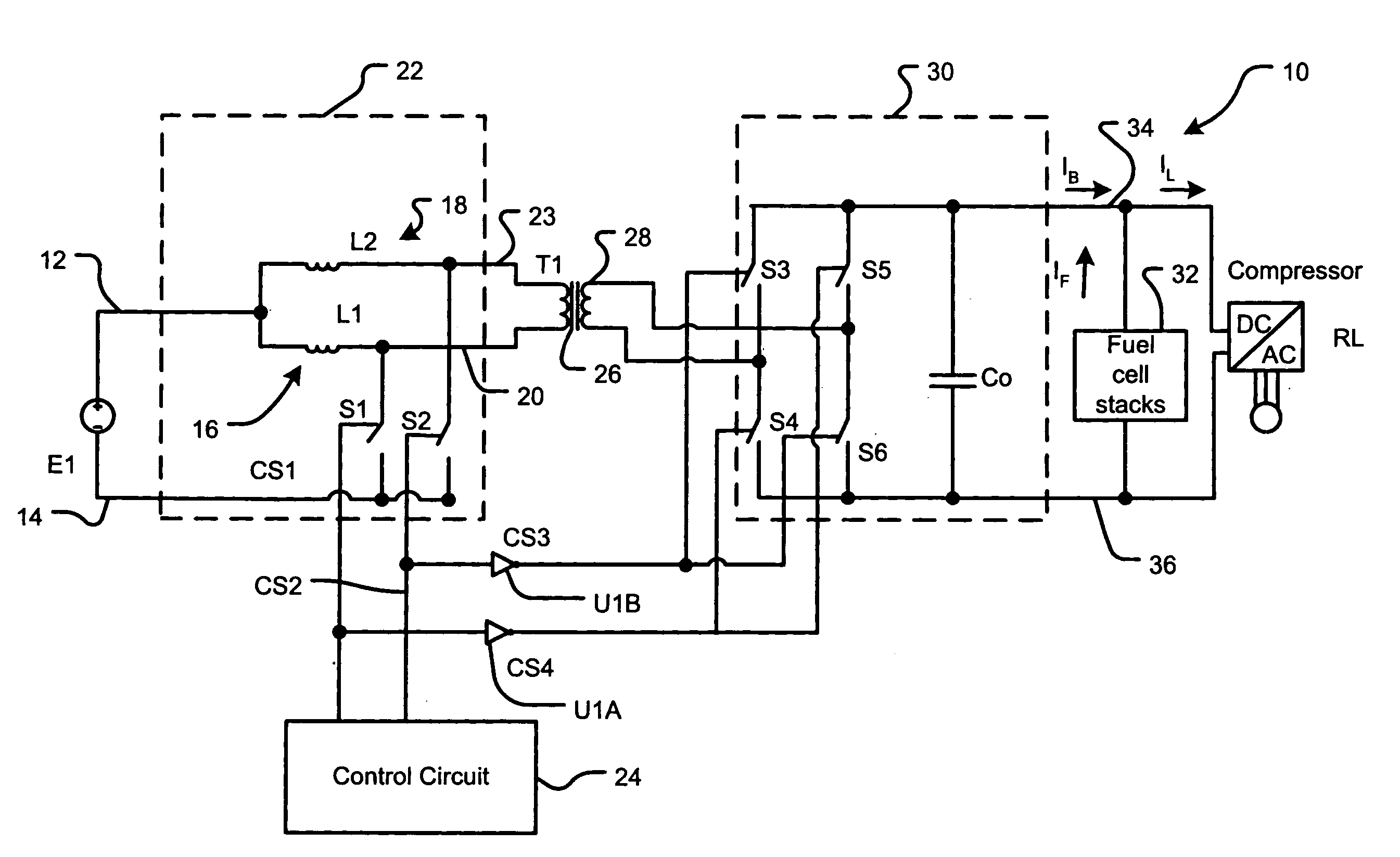
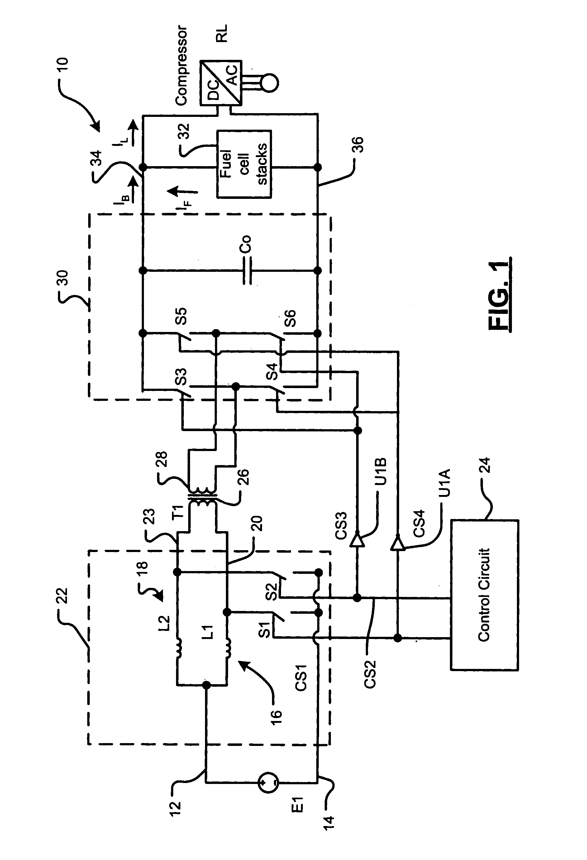
[0017]In some configurations of the present invention and referring to FIG. 1, a power conversion circuit 10 comprises a current section 22. Current section 22 is configured to receive an input voltage from a voltage source E1 between a first node 12 and a node 14 that can be a common ground. For example, voltage source E1 may be an automobile battery supplying 9 to 15 volts DC. Common ground 14 may be a vehicle chassis or a conductive portion thereof. The vehicle chassis may be an automobile chassis, and voltage source E1 may be a rechargeable storage battery. However, the present invention is not limited to use in automobiles or other vehicles.

[0018]Current section 22 in some configurations comprises a pair of switched circuit branches 16, 18 each of which comprises an inductor L1, L2, respectively. (The proximity o...


PUM


Abstract

A power conversion circuit includes a current section, a transformer, and a voltage section. The current section includes inductors configured to produce a boosted output voltage from a voltage sourse when then current section is operating in a forward direction. The transformer includes a primary winding electrically coupled to the secondary winding and configured to drive a load. The voltage section includes a pluralaty of balancing switchtes configured to actively driven to provide a DC voltage to the load. The balancing switches balance energy between the current section and the voltage section when the power conversion circuit is the load and operating in the forward direction.

Description

FIELD OF THE INVENTION[0001]The present invention relates to switching power conversion circuits, including, but not limited to, bi-directional power conversion circuits.BACKGROUND OF THE INVENTION[0002]Bi-directional, isolated DC-to-DC inverters are useful in a wide range of applications. Examples of such applications include, but are not limited to, uninterruptible power supplies, battery charging systems, and auxiliary power supplies for hybrid electrical vehicles.[0003]It has been recognized that two-inductor boost converters suffer from limited output voltage regulation range when operated at low duty cycles. More particularly, when a load is below the minimum input power of a converter circuit of this type, further decreases in the load result in abnormal increases in output voltage due to excess energy storage in the inductors. Yan et al. have proposed a solution to avoid these increases in output voltage. (“Isolated Two-Inductor Boost Converter with One Magnetic Core,” Eight...

Claims


Application Information

Patent Timeline
Patent Type & Authority Patents(United States)
IPC IPC(8): H02J7/00H02M3/335
CPCH02M3/33569H02M3/33592Y02B70/1475Y02B70/10
Inventor KAJOUKE, LATEEF A.CHEN, KEMING A.LAZAR, JAMES F.
Owner GM GLOBAL TECH OPERATIONS LLC
Learn More