System and method for sensor less magnetic field control of a motor

a sensor and magnetic field technology, applied in the direction of multiple motor speed/torque control, synchronous motor starter, electronic commutator, etc., can solve the problems of system installation and maintenance complexity, undesirable oscillation, and “stall” condition

Active Publication Date: 2006-10-03
ALLIED MOTION CANADA
View PDF25 Cites 39 Cited by
  • Summary
  • Abstract
  • Description
  • Claims
  • Application Information

AI Technical Summary

Benefits of technology

[0024]The motor controller may switch from open loop mode to phase locked loop (or closed loop) mode and back again at a threshold speed. These transitions may be performed with minimal torque disturbance an with no position loss. The motor controller may continually track and accumulate any position related errors and recover the errors when load and speed conditions permit.

Problems solved by technology

Operating stepper motors without any position feedback may cause problems in situations where the rotor “lags” behind the intended rotor position by being a number of steps, or in steps being “lost” and never recovered if the rotor lags behind the intended position too much.
Further, without any positional feedback, resonance problems may occur leading to a “stall” condition, such as when the magnetic field created by the stators of the motor is such that it holds the rotor in place rather than rotating it, cannot be detected and corrected by a motor controller.
Additionally, even if resonance does not lead to a stall conditions, undesirable oscillations would result from the resonance.
Positional feedback sensors may be incorporated into a motor to monitor the position of the rotor optically, but such systems may be complicated to install and maintain, and furthermore may require substantially more control circuitry or software modules to implement.

Method used


Image

  • System and method for sensor less magnetic field control of a motor
  • System and method for sensor less magnetic field control of a motor
  • System and method for sensor less magnetic field control of a motor

Examples


Embodiment Construction

[0043]The description which follows, and the embodiments described therein, are provided by way of illustration of an example, or examples, of particular embodiments of the principles of the present invention. These examples are provided for the purposes of explanation, and not limitation, of those principles and of the invention. In the description, which follows, like parts are marked throughout the specification and the drawings with the same respective reference numerals.

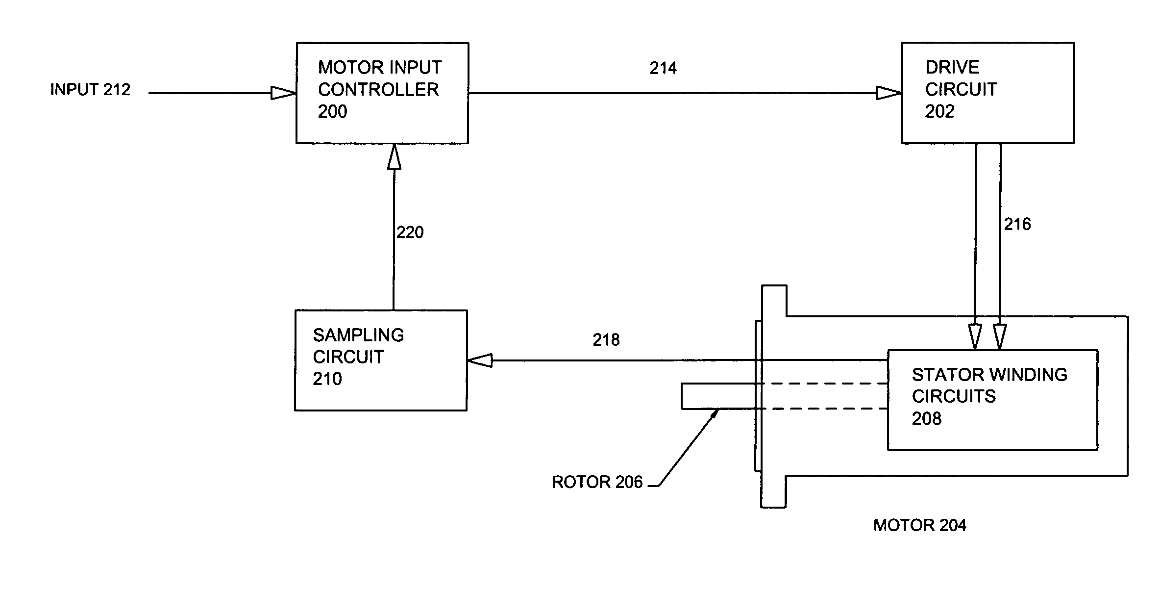
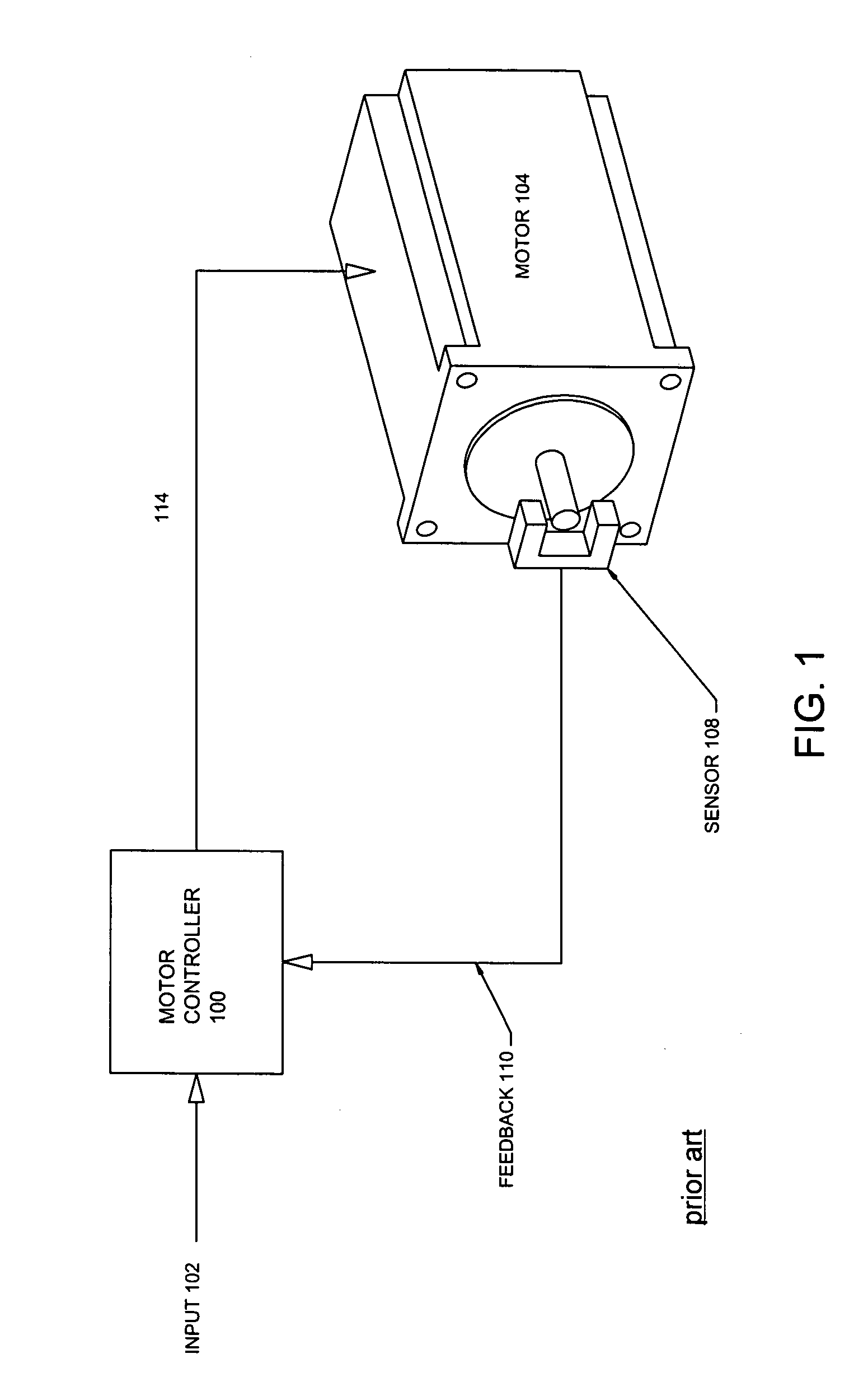
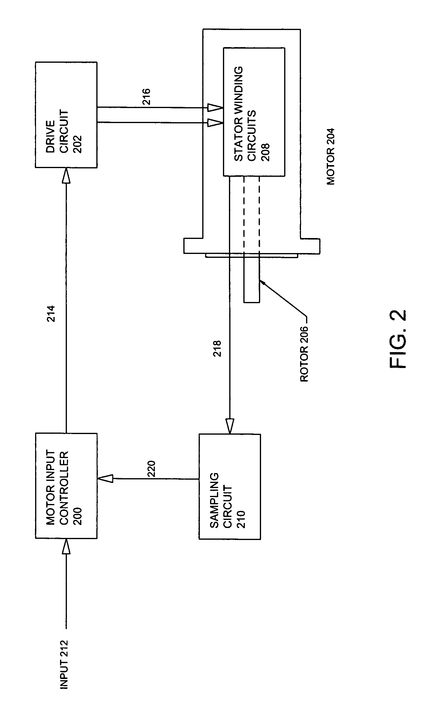
[0044]Referring to FIG. 1, a prior art motor controller 100 with sensor 108 providing position feedback is shown. In such an implementation, input signals 102 are provided to prior art motor controller 100, which then provides control signals 214 to motor 104, which then causes the “stepping” motion of rotor 106. Feedback in such a prior art implementation is provided by sensor 108, which may be an optical sensor, to determine the position of rotor 106. This feedback signal is then provided as feedback signals 1...


PUM


Abstract

A system and method for sensor less control of a stepper motor is described. The system and method includes estimation of the position of a rotor of the motor by way of sensing circuitry on the windings of the motor, without the use of positional sensors. The system and method of stepper motor control further includes magnetic field optimization for increasing the torque generating component of a magnetic field generated by stators of the motor, and magnetic field weakening for countering some of the effects of back electromotive force generated by the magnetic rotor.

Description

[0001]This application claims the benefit of U.S. Provisional Application No. 60 / 603,287, filed Aug. 23, 2004.FIELD OF INVENTION[0002]The present invention relates to a system and method for sensor less magnetic field control of a motor, such as a stepper motor.BACKGROUND OF THE INVENTION[0003]A motor may operate without any position feedback and rely on a motor's inherent characteristics to control the position of the rotor by energizing particular stators of the motor. This manner of motor operation may typically be found in stepper motors, wherein the rotor of a motor rotates by a specific number of degrees in response to input electrical signals to energize particular stators of such motors.[0004]Stepper motors typically convert digital pulse inputs to analog output rotor movement. Typically, in response to an input pulse of electrical signal, the rotor of a stepper motor rotates by a design-specified number of degrees, or a step. Stepper motors are typically classified as perma...

Claims


Application Information

Patent Timeline
Patent Type & Authority Patents(United States)
IPC IPC(8): H02P7/06
CPCH02P6/182H02P8/34
Inventor MACKAY, DAVID KYLE
Owner ALLIED MOTION CANADA
Why Eureka
Try Eureka