System and method for detecting the axial position of a shaft or a member attached thereto
a technology of axial position and shaft, which is applied in the direction of magnetic property measurement, material magnetic variables, instruments, etc., can solve the problems of limited stroke, expensive magnets with strong magnetic properties, and restricted cylinder position sensors
- Summary
- Abstract
- Description
- Claims
- Application Information
AI Technical Summary
Benefits of technology
Problems solved by technology
Method used
Image
Examples
sixth embodiment
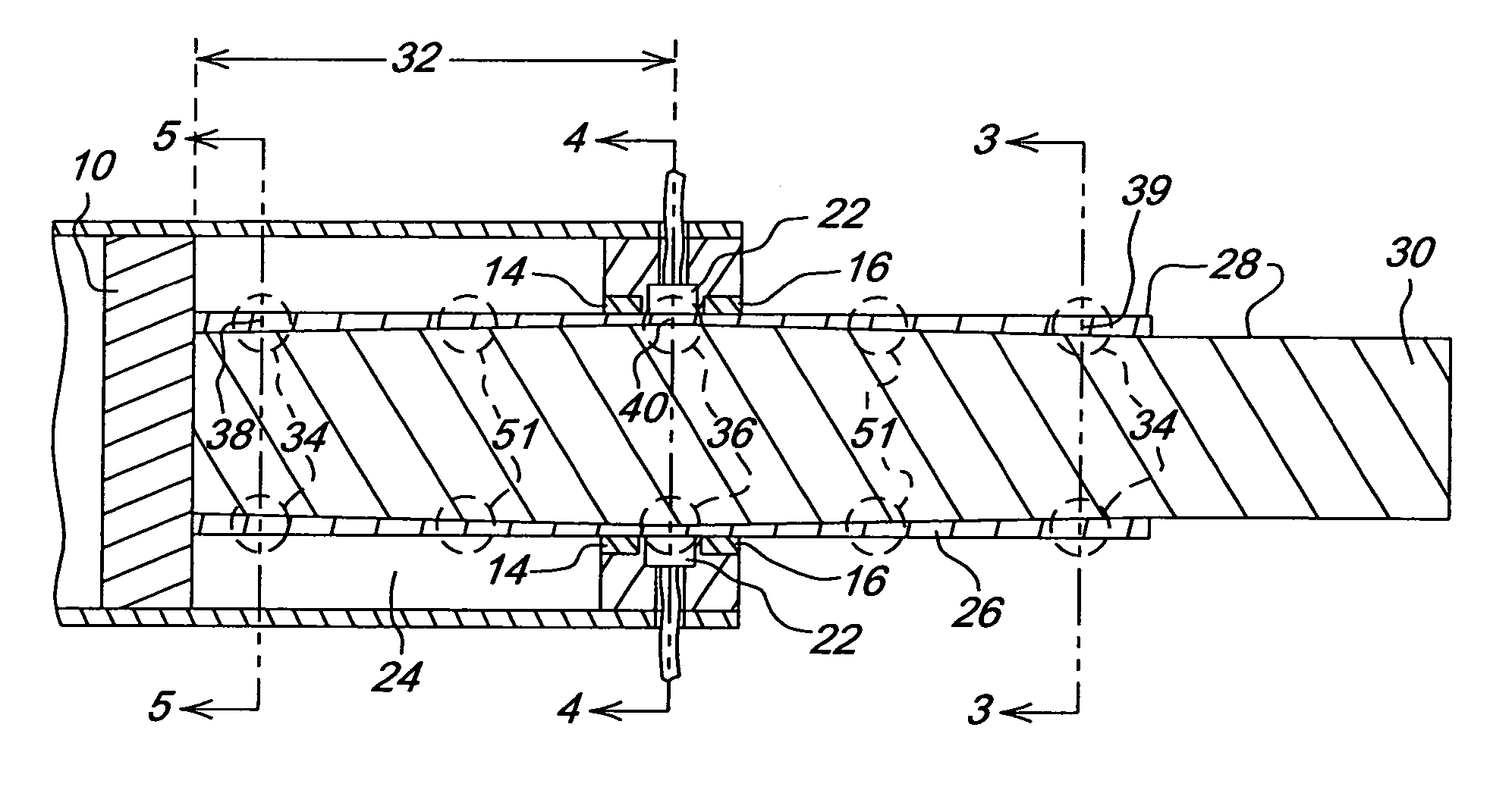
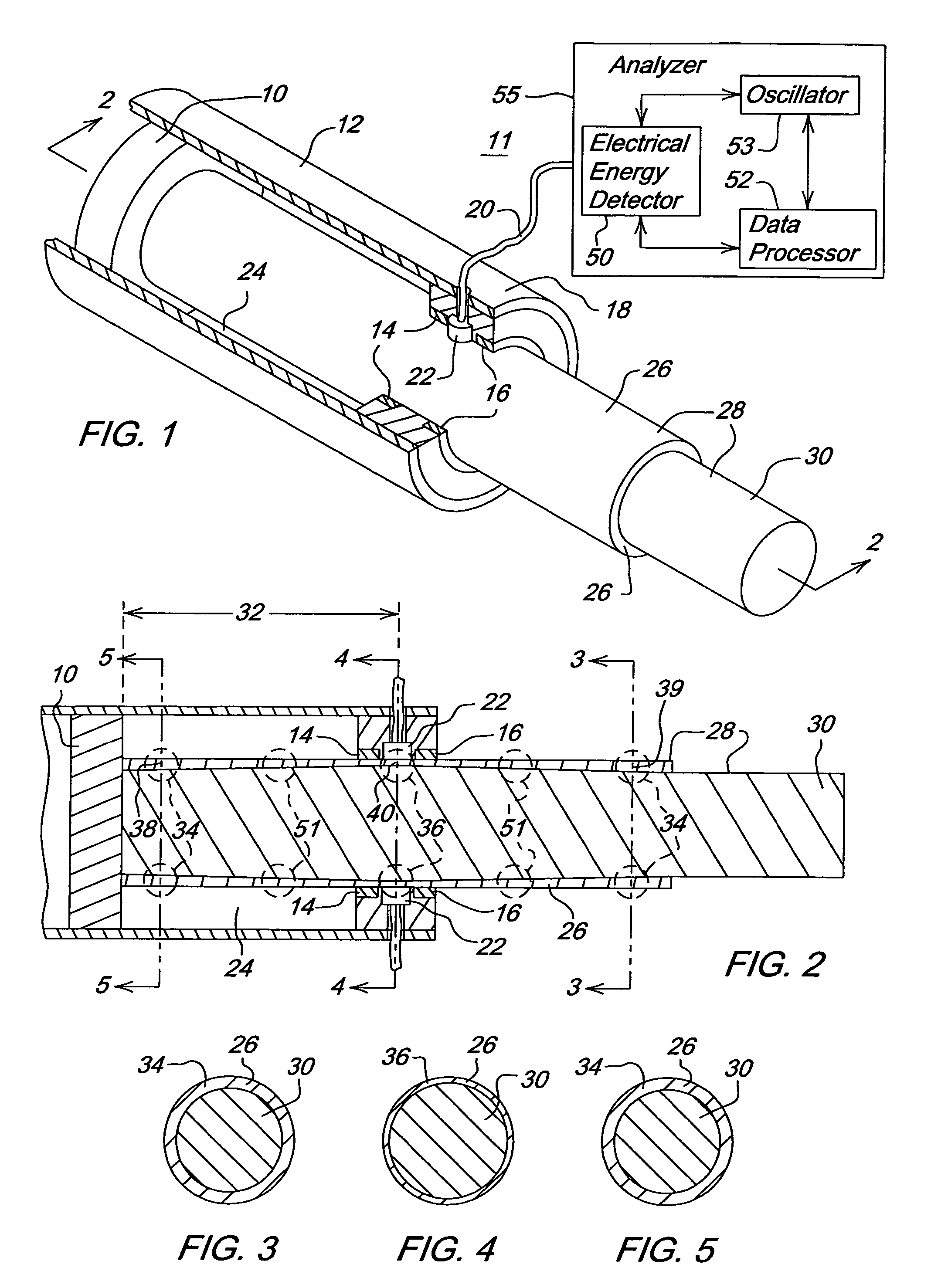
[0031]y=√{square root over (ρ)} / πμoμf, where ρ is the resistivity of the shaft 28, μo is the magnetic permeability of the vacuum, μ is the relative permeability of the shaft 28, and f is the frequency of the induction current. Under the shaft 28, the first hardened metallic region 36 and the second hardened metallic region 34 are formed in accordance with the following equation:
[0032]y=k√{square root over (f)}, where k is a constant based on a metallic material at a given temperature range and f is the frequency of the induction current. Any of the foregoing alternate embodiments of the shaft 28 may be applied to the configuration of FIG. 1 and FIG. 2, for example. Further, some of the foregoing alternate embodiments are described in greater detail in conjunction with FIG. 10 through FIG. 11.
[0033]Although the shaft 28 may be constructed of various metals or alloys that fall within the scope of the invention, in one embodiment the shaft represents a steel or iron-based alloy, which ...
first embodiment
[0052]FIG. 12 is consistent with two alternative embodiments. Under FIG. 12, first hardened metallic region 134 comprises a generally rectangular strip with a first radial depth; the second hardened metallic region 136 is spaced apart from the first hardened metallic region 134 and has a second radial depth that is different from the first radial depth. Different radial depths means the first radial depth may be radially greater or less than the second radial depth. Independent of the radial depths of the rectangular strips, each rectangular strip on a shaft may be axially longer or shorter than the other rectangular strip. The intermediate hardened metallic region 135 lies between the first hardened metallic region 134 and the second hardened metallic region 136. As shown in FIG. 12, the intermediate hardened metallic region 135 is thinner than the first hardened metallic region 134; the intermediate hardened metallic region 135 is thinner than the second metallic region 136.
second embodiment
[0053]Under a shaft 128 of FIG. 12, the first hardened metallic region 134 is a generally annular region with a first radial depth; the second hardened metallic region 136 is a generally annular region spaced apart from the first hardened metallic region 134. The intermediate hardened metallic region 135 lies between the first hardened metallic region 134 and the second hardened metallic region 136. The second radial depth is different from (e.g., lesser or greater than) the first radial depth. Independent of the radial depths of the annular regions, each annular region on a shaft may be axially longer or shorter than the other rectangular strip
[0054]If the first hardened metallic region 134 at a first longitudinal position 138 is aligned with the sensor 22, the shaft 128 has a first known axial displacement with respect to the cylinder 12. If the intermediate metallic region 135 is aligned with the sensor 22, the shaft has a second known axial displacement (e.g., an axial displacem...
PUM
| Property | Measurement | Unit |
|---|---|---|
| radial depth | aaaaa | aaaaa |
| metallic | aaaaa | aaaaa |
| frequency | aaaaa | aaaaa |
Abstract
Description
Claims
Application Information
 - R&D
- Intellectual Property
- Life Sciences
- Materials
- Tech Scout
- Unparalleled Data Quality
- Higher Quality Content
- 60% Fewer Hallucinations
Browse by: Latest US Patents, China's latest patents, Technical Efficacy Thesaurus, Application Domain, Technology Topic, Popular Technical Reports.
© 2025 PatSnap. All rights reserved.Legal|Privacy policy|Modern Slavery Act Transparency Statement|Sitemap|About US| Contact US: help@patsnap.com


