
Magnetic field mapping during SSFP using phase-incremented or frequency-shifted magnitude images

a phase-increment or frequency-shifted magnitude image and magnetic field mapping technology, applied in the field of magnetic field mapping during, can solve the problems of unsatisfactory image distortion and sometimes artifacts, and the magnetic field mapping so generated is susceptible to interference from chemical shifts

Inactive Publication Date: 2006-10-03
TOSHIBA AMERICA MRI
View PDF8 Cites 24 Cited by
  • Summary
  • Abstract
  • Description
  • Claims
  • Application Information

AI Technical Summary

Problems solved by technology

Deviations from this linear relationship can cause undesired image distortions and sometimes artifacts.
Since the phases of the echo signals are influenced by field inhomogeneities as well as chemical shifts, the magnetic field maps so generated are susceptible to interference from chemical shifts.

Method used

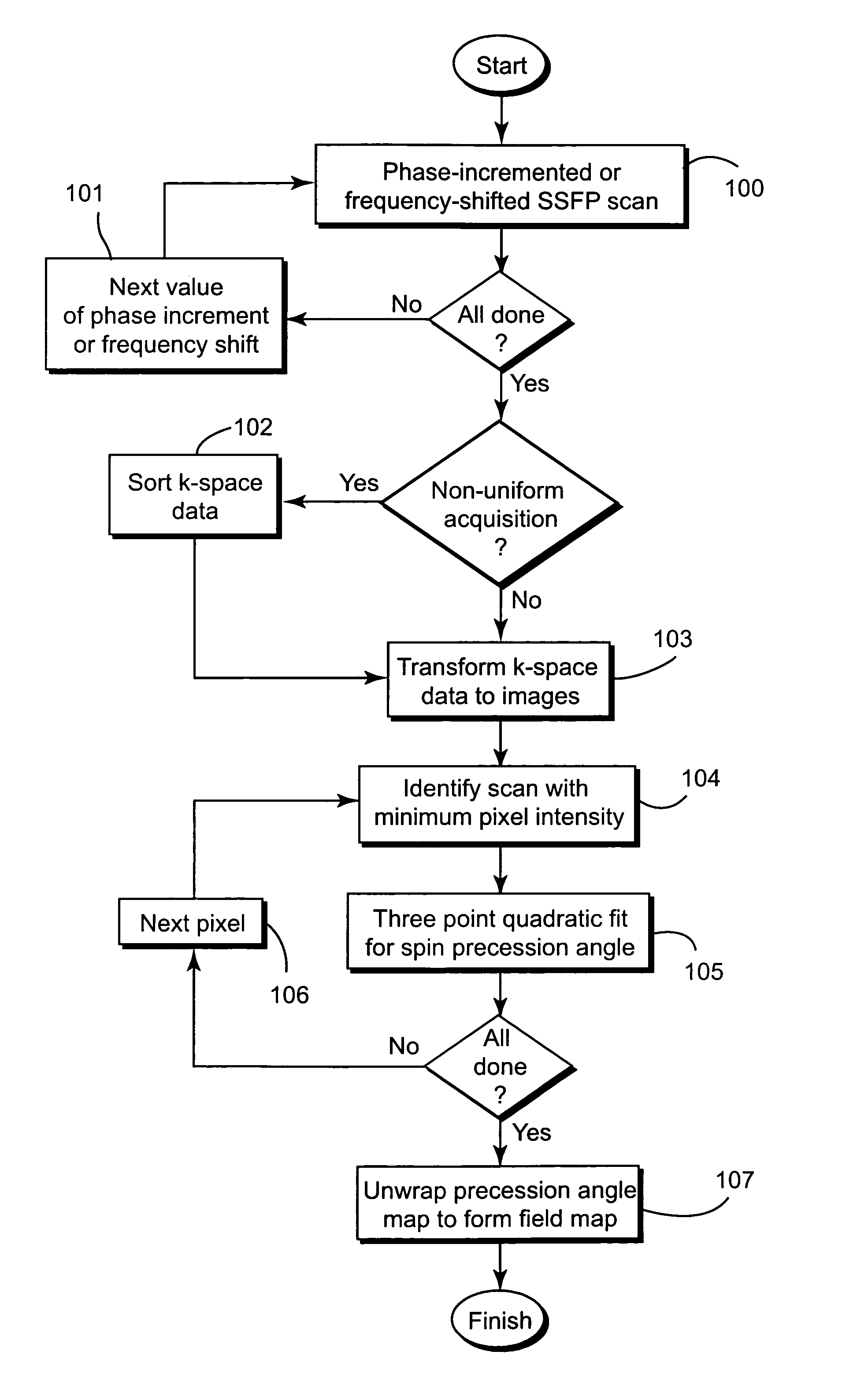
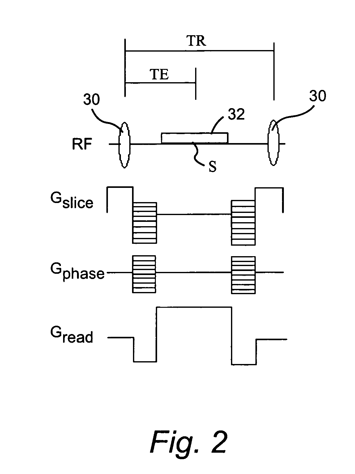

Image

  • Magnetic field mapping during SSFP using phase-incremented or frequency-shifted magnitude images
  • Magnetic field mapping during SSFP using phase-incremented or frequency-shifted magnitude images
  • Magnetic field mapping during SSFP using phase-incremented or frequency-shifted magnitude images

Examples


Embodiment Construction

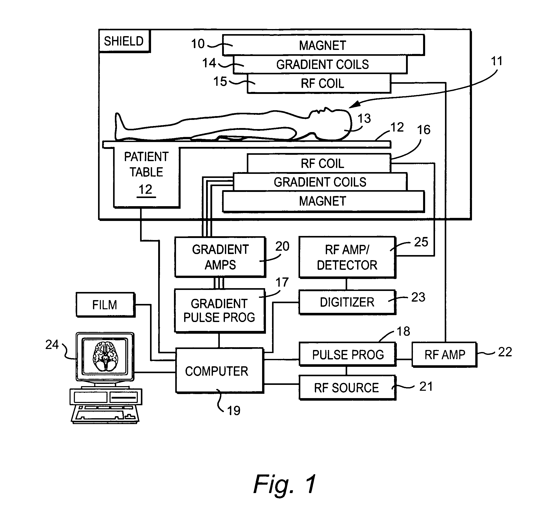
[0016]As shown in FIG. 1, a magnetic resonance imaging (MRI) system typically includes a large magnet 10 to impose a static magnetic field (B0), gradient coils 14 for imposing spatially distributed gradient magnetic fields (Gx, Gy, and Gz) along three orthogonal coordinates, and RF coils 15 and 16 to transmit and receive RF signals to and from the selected nuclei of the object being imaged. The object 13 lies on a movable table 12 such that a portion of the object to be imaged is moved, in three-dimensions, in an “imaging volume”11 between the magnet and coils, which defines a field of view (FOV) of the MRI system.

[0017]To acquire MRI data, the MRI system generates magnetic gradient and RF nutation pulses via MRI pulse sequence controllers 17 and 18 that operate under the control of a programmable processor 19, e.g., a workstation computer 24. In addition, the processor 19 controls a gradient pulse amplifier 20, and RF source and amplifier circuits 21 and 22. The MR signal circuits ...


PUM


Abstract

A system has been developed for mapping the magnetic field during a balanced steady-state free precession (SSFP) sequence. Field maps are generated by analyzing the magnitude of images acquired using the SSFP imaging sequences with phase increment or frequency shift. The system maps the magnetic field relevant to the imaging sequence and need not rely on phase information. The field maps may be applied to adjust the hardware for correcting the field anomalies contained in the maps. The field maps may also be used for separation of water and fat signals in SSFP imaging.

Description

BACKGROUND OF THE INVENTION[0001]Conventional magnetic resonance imaging (MRI) methods rely on a linear relationship between magnetic fields and spatial positions of the nuclear spins within the object being imaged. This relationship is realized by using a combination of homogeneous magnets and linear gradient coils. Deviations from this linear relationship can cause undesired image distortions and sometimes artifacts.[0002]Field anomalies are deviations of magnetic fields from prescribed values. Anomalies can be static as well as sequence-induced. Static anomalies may occur from, for example, field inhomogeneities produced by the magnet used to generate the main static magnetic field. Sequence-induced anomalies may occur from, for example, eddy-currents or the Maxwell fields.[0003]Two remedies often used for correcting anomalies in magnetic field are: (i) minimization of inhomogeneities by shimming the magnetic field using special shimming hardware, and (ii) post data acquisition i...

Claims


Application Information

Patent Timeline
Patent Type & Authority Patents(United States)
IPC IPC(8): G01V3/00
CPCG01R33/5613G01R33/56563
Inventor ZHANG, WEIGUO
Owner TOSHIBA AMERICA MRI
Learn More